Multi-step bore turbocharger

a turbocharger and multi-step technology, applied in the field of turbochargers, can solve the problems of increasing the cost, physical and assembly complexity of the turbocharger,

Active Publication Date: 2020-08-18
GM GLOBAL TECH OPERATIONS LLC
View PDF17 Cites 2 Cited by
  • Summary
  • Abstract
  • Description
  • Claims
  • Application Information

AI Technical Summary

Benefits of technology

[0005]According to several aspects of the present disclosure, a turbocharger includes a compressor housing defining a compressor chamber. The turbocharger also includes a turbine housing defining a turbine chamber, and a center housing disposed axially between the compressor housing and the turbine housing. A turbine wheel is disposed in the turbine chamber, and a turbine shaft is connected to the turbine wheel. A compressor wheel is disposed in the compressor chamber and connected to the turbine shaft opposite from the turbine wheel. The compressor wheel has a shank with a cylindrical outer diameter portion and a cylindrical reduced diameter portion. The cylindrical reduced diameter portion has a diameter smaller than the cylindrical outer diameter po

Problems solved by technology

Utilizing an increased number of piston ring seals can increase

Method used


Image

  • Multi-step bore turbocharger
  • Multi-step bore turbocharger
  • Multi-step bore turbocharger

Examples


Embodiment Construction

[0031]The following description is merely exemplary in nature and is not intended to limit the present disclosure, application, or uses.

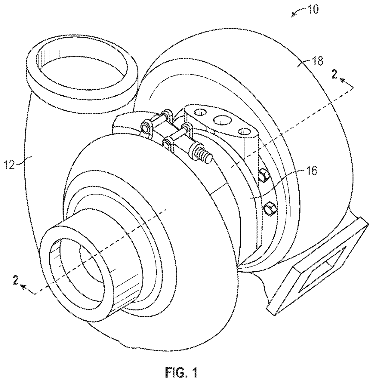
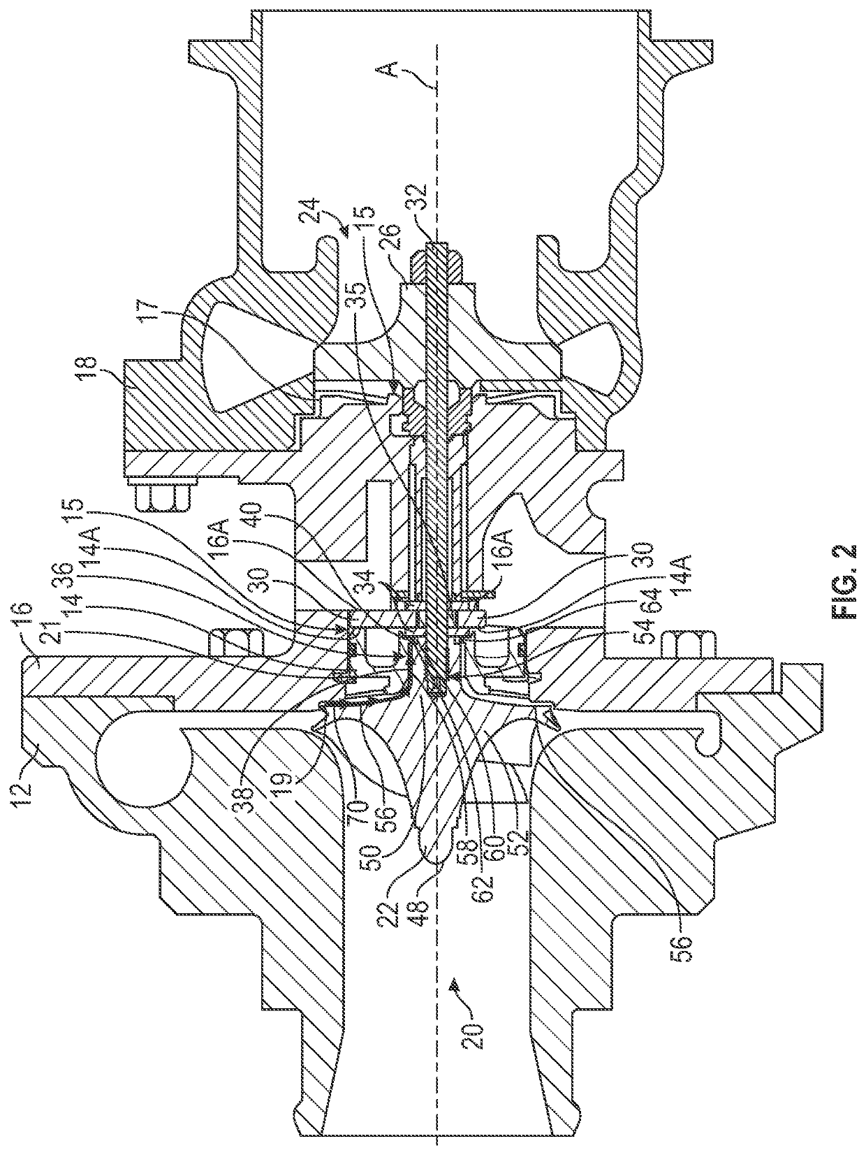
[0032]Referring to FIGS. 1 and 2, a turbocharger according to an exemplary embodiment of the present disclosure is shown generally at 10. The turbocharger 10 may be of any of a variety of different turbocharger types without departing from the scope or intent of the present disclosure. For example, the turbocharger 10 may be a single scroll turbocharger, a twin-scroll turbocharger, a variable geometry turbocharger, an electric turbocharger, or the like. In one aspect, the turbocharger 10 includes a compressor housing 12 with a backplate 14. The turbocharger 10 further includes a center housing 16. In some examples, the center housing 16 has a substantially cylindrical shape and defines a cavity 15. The cavity 15 has opposite ends 17, 19 facing the compressor housing 12 and a turbine housing 18 respectively. One of the opposite ends 17, 19 is an open...


PUM


Abstract

A turbocharger includes a compressor housing, turbine housing, and center housing between the compressor and turbine housings. A turbine wheel is disposed in the turbine housing on a turbine shaft. A compressor wheel having a shank is disposed in the compressor housing on the turbine shaft. The shank has outer and reduced portions. The reduced portion has a smaller diameter than the outer portion. A backplate is mounted to the compressor housing adjacent the compressor wheel and defines a stepped cylindrical bore with a maximum diameter portion and a minimum diameter portion having a smaller diameter than the maximum portion. The outer portion is disposed in the maximum portion. The reduced portion is disposed in the minimum portion. The outer diameter of the shank is greater than or equal to the minimum diameter of the backplate, and the stepped cylindrical bore and the shank define a variable width gap.

Description

INTRODUCTION[0001]The present disclosure relates to an internal combustion engine having forced induction, and in particular, a turbocharger.[0002]Turbochargers increase a volume and density of air drawn into the internal combustion engine during an intake stroke. More specifically, turbochargers provide positive pressure to the intake tract of an internal combustion engine by using a compressor wheel in a compressor housing coupled to and driven by an exhaust turbine in a turbine housing of the turbocharger. A pressure differential exists between the compressor housing and the center housing of the turbocharger and can result in air and / or lubricant passing between the compressor housing and the center housing under high-pressure differentials.[0003]An annular piston ring seal is often used to limit the amount of air and / or lubricant that may pass between the compressor housing and the center housing when the turbocharger is being used to generate boost. The piston ring seals do pr...

Claims


Application Information

Patent Timeline
IPC IPC(8): F02C6/12F02B39/14F04D29/12F02B33/40
CPCF02B39/14F02B33/40F02C6/12F04D29/122F05D2240/55F05D2220/40F04D17/10F04D29/4206F04D29/056F04D29/083F01D25/183F05D2240/58F05D2240/53F01D5/046F01D5/025
Inventor BEGIN, LOUISDENG, DINGFENGGARG, RACHIT
Owner GM GLOBAL TECH OPERATIONS LLC
Why Eureka
Try Eureka