
Methods and system for operating an engine

a technology of internal combustion engine and system, applied in the direction of machines/engines, electric control, ignition automatic control, etc., can solve the problems of engine misfire, engine misfire in response, engine misfire, etc., to improve engine misfire detection and mitigation, and improve signal to noise ratio. , the effect of improving the signal to noise ratio

Active Publication Date: 2020-09-01
FORD GLOBAL TECH LLC
View PDF7 Cites 0 Cited by
  • Summary
  • Abstract
  • Description
  • Claims
  • Application Information

AI Technical Summary

Benefits of technology

This patent describes a way to detect and mitigate engine misfire using a sensor that detects changes in the engine's compression ratio. By adjusting the engine actuator based on these changes, misfire can be detected over a wider range of engine operating conditions. This approach improves engine emissions, torque production, and overall performance. Overall, this patent provides better detection and mitigation of engine misfire and can adapt to different operating conditions.

Problems solved by technology

An engine may misfire from time t0 time due to various operating conditions.
For example, an engine may misfire in response to a lean engine air-fuel ratio.
Further, the engine may misfire in response to improperly timed ignition spark.
However, there may be some engine operating conditions where it may be difficult to assess whether or not an engine has misfired because the engine may exhibit torsional vibrations of the engine's crankshaft.
If engine misfire is not determined during these engine operating conditions, engine torque output may decline and undesirable engine emissions may increase.
Further, engine misfire may be determined from output of a sensor coupled to an engine compression ratio changing linkage during engine operating conditions when crankshaft torsional vibrations are high.
In addition, the approach may suspend or change methods for determining engine misfire during conditions where one engine misfire detection method may be less reliable.

Method used


Image

  • Methods and system for operating an engine
  • Methods and system for operating an engine
  • Methods and system for operating an engine

Examples


Embodiment Construction

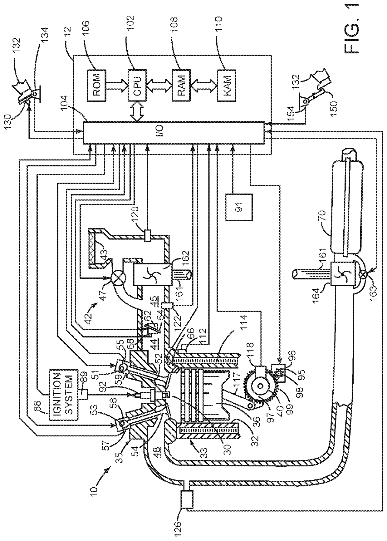
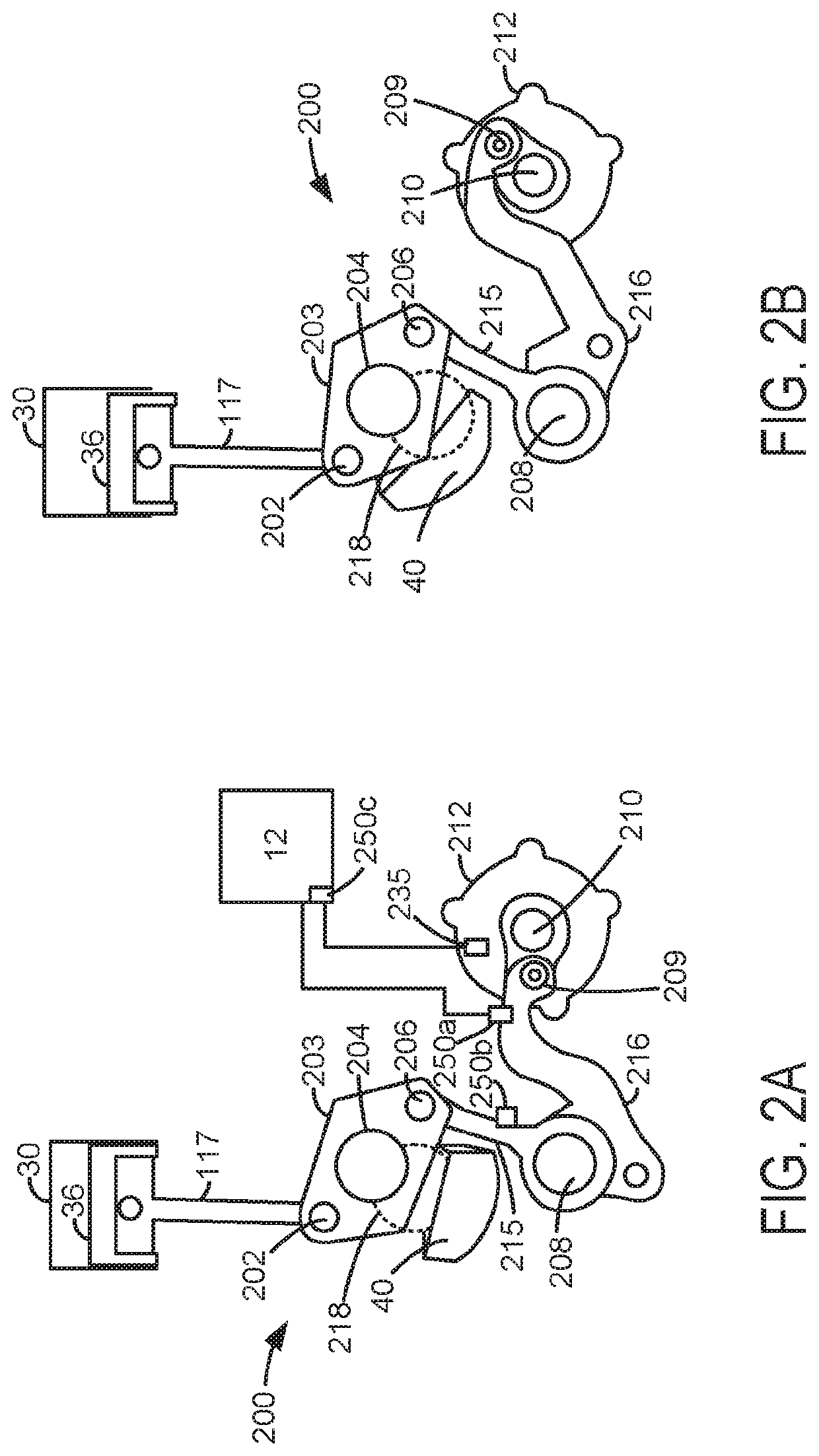
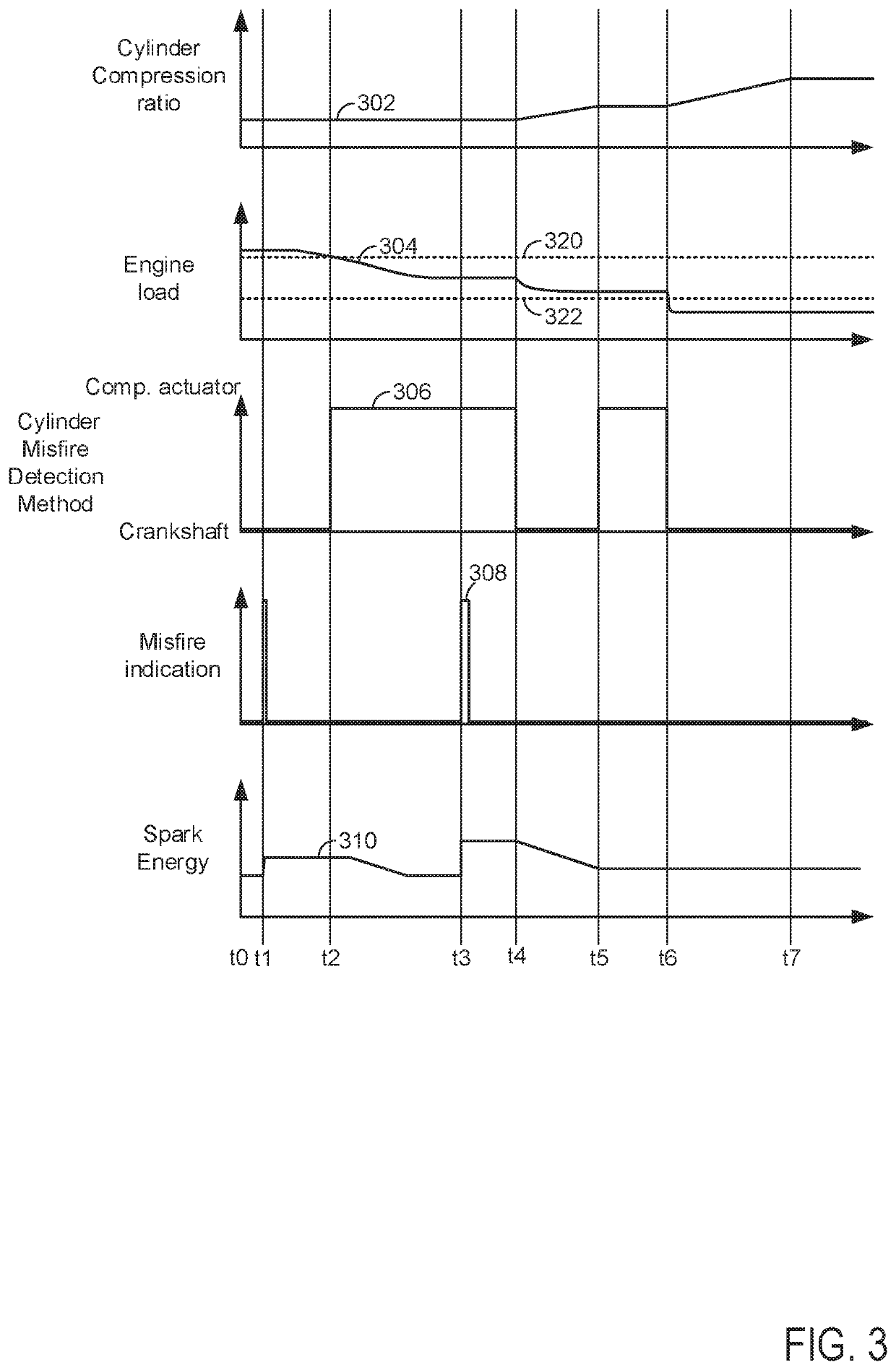
[0014]The present description is related to operating a variable compression ratio engine and determining the presence or absence of engine misfire (e.g., lack of combustion in the cylinder or where less than a threshold amount (15%) of an air-fuel mixture in a cylinder combusts during a cycle of the cylinder). The engine may be of the type shown in FIG. 1 or it may be a diesel engine. The engine may include one or more cylinder compression ratio changing linkages as shown in FIGS. 2A and 2B. The engine may be operated according to the method of FIG. 4 to provide the operating sequence shown in FIG. 3. Engine misfire detection methods may be invoked in response to engine operating conditions as shown in FIG. 5.

[0015]Referring to FIG. 1, internal combustion engine 10, comprising a plurality of cylinders, one cylinder of which is shown in FIG. 1, is controlled by electronic engine controller 12. Engine 10 is comprised of cylinder head 35 and block 33, which include combustion chamber ...


PUM


Abstract

Systems and methods for operating an engine that includes a compression ratio linkage for adjusting engine compression ratio are described. The systems and methods provide different ways of diagnosing the presence or absence of engine misfire in response to engine operating regions that may be more or less prone to torsional engine crankshaft vibration. In one example, engine misfire may be determined responsive to force applied to an engine compression ratio changing linkage.

Description

FIELD[0001]The present description relates to methods and a system for operating an internal combustion engine. The methods and systems may be particularly useful determining the presence or absence of engine misfire for an engine that has a compression ratio adjustment linkage.BACKGROUND AND SUMMARY[0002]An engine may misfire from time t0 time due to various operating conditions. For example, an engine may misfire in response to a lean engine air-fuel ratio. Further, the engine may misfire in response to improperly timed ignition spark. One way to determine whether or not the engine may have misfired may be by monitoring engine acceleration during an engine cycle. If engine acceleration during an engine cycle is less than a threshold, it may be judged that the engine has misfired. However, there may be some engine operating conditions where it may be difficult to assess whether or not an engine has misfired because the engine may exhibit torsional vibrations of the engine's cranksh...

Claims


Application Information

Patent Timeline
Patent Type & Authority Patents(United States)
IPC IPC(8): F02D41/14F02D15/02G01M15/11F02P5/15
CPCF02D15/02G01M15/11F02D41/1495F02D41/1498F02P5/1512F02D2200/1015F02D2700/03F02D2200/101Y02T10/40
Inventor GLUGLA, CHRISTOPHER PAULSURNILLA, GOPICHANDRAALI, IMTIAZALOBIEDAT, LYTH
Owner FORD GLOBAL TECH LLC
Learn More