
Direct thermal injection thermal analysis

a thermal analysis and injection technology, applied in the field of thermal analysis, can solve the problems of slow heat and cooling of traditional instruments, high energy consumption, and frequent maintenance and replacement, and achieve the effects of reducing the overall instrument cost of goods sold, fast, dynamic and economical analysis, and eliminating costly high-temperature furnaces

Active Publication Date: 2020-11-03
TA INSTR WATERS LLC
View PDF28 Cites 0 Cited by
  • Summary
  • Abstract
  • Description
  • Claims
  • Application Information

AI Technical Summary

Benefits of technology

[0009]The methods and apparatus of the present disclosure provide several advantages over the prior art. The direct application of thermal energy in the form of electromagnetic radiation allows for fast, dynamic and economical analyses. Delivery of electromagnetic radiation to a sample, such as by a laser, provided the ability to deliver energy into a material to effect a temperature change rapidly and controllably.
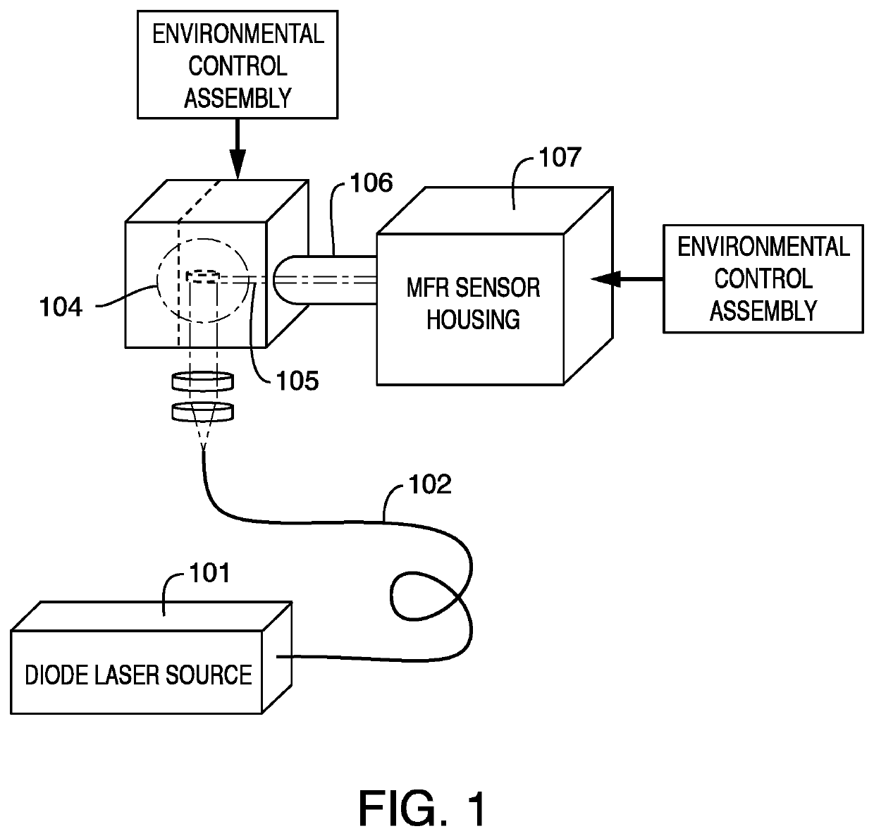
[0010]The methods and apparatus of the present disclosure can utilize highly focused electromagnetic radiation energy in techniques common to commercially viable benchtop instruments, such as a thermal gravimetric analyzer instrument. The use of a laser source in conjunction with a containment vessel can permit not only the elevation of sample temperatures in a controllable manner, but do so under controlled atmospheric / environmental conditions. The use of direct application of electromagnetic radiation also allows for a reduction in overall instrument cost of goods sold by elimination of costly high temperature furnaces, support electronics, and heat exchangers. The reduced power consumption and direct heating of the sample also eliminates thermal shock issues associated with furnace components.

Problems solved by technology

Traditional instruments are slow to heat and cool, require a lot of energy to change sample temperature, and require regular routine maintenance and replacement.

Method used


Image

  • Direct thermal injection thermal analysis
  • Direct thermal injection thermal analysis
  • Direct thermal injection thermal analysis

Examples


example 1

vimetric Analyzer Having Direct Thermal Injection

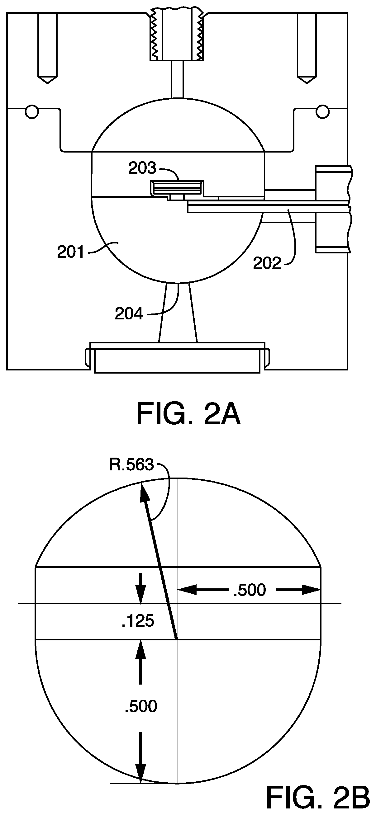
[0061]The instrument employed a balance and a portion of electronics from a TA Instruments' Q600 (SDT). The components were mated to an off-the-shelf diode laser system (DILAS MINI 808 nm) custom designed cavity, and off-the-shelf control electronics. The instrument was fitted with a containment cavity made of brass. The dimensions of the cavity are similar to those shown and described in FIG. 2B. The upper radius was 0.5625 inches. The lower radius was 0.5 inches. The cavity included a cylindrical section had a height of about 0.25 inches and a radius of about 0.5 inches. The interior surface of the cavity was coated with gold to provide a reflective surface.

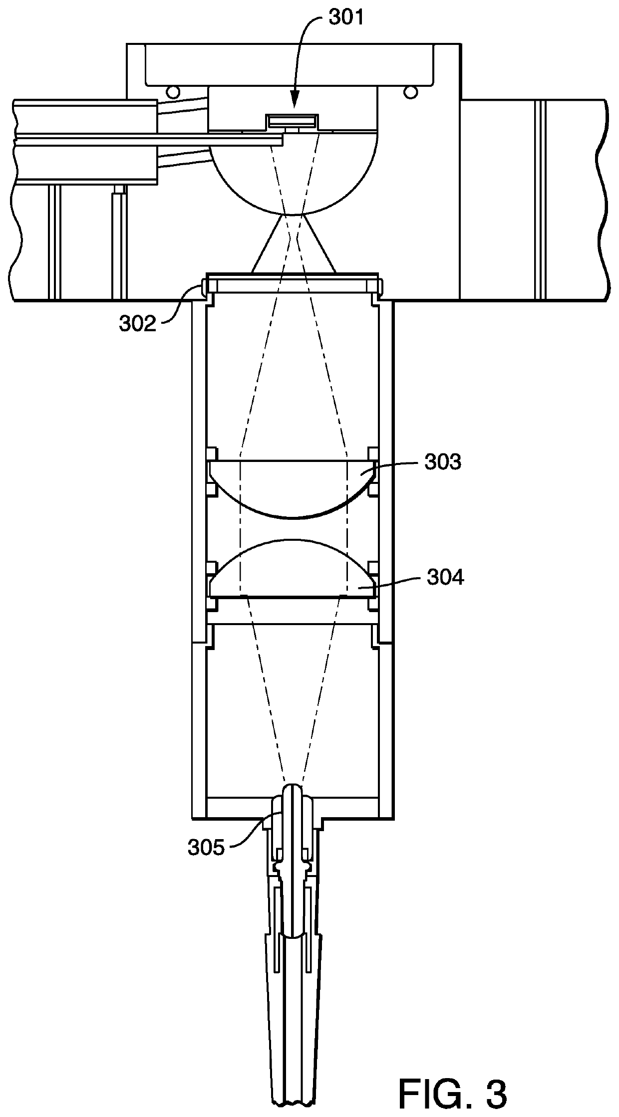
[0062]The diode laser generated the electromagnetic radiation as a wavelength of 808 nm. The power of the laser to heat the sample was about 50 W. The laser was fitted with a fiber optic (DILAS, MINI, 400 um core, 2 m length fiber) to transmit the light from the laser to the opti...


PUM

PropertyMeasurementUnit
wavelengthaaaaaaaaaa
operating temperatureaaaaaaaaaa

Abstract

The present disclosure relates generally to thermal analyses having direct application of thermal energy to a sample.

Description

RELATED APPLICATIONS[0001]This application claims the benefit of U.S. Provisional Patent Application Ser. No. 62 / 425,169 titled “Direct Thermal Injection Thermal Analysis” filed on Nov. 22, 2016, the contents of which is herein incorporated by reference in its entirety.TECHNICAL FIELD[0002]The present disclosure relates generally to thermal analyses having direct application of thermal energy in the form of electromagnetic radiation (e.g., light) to a sample.BACKGROUND OF THE INVENTION[0003]The field of thermal analysis is a branch of materials science where the properties of materials are studied as they change with temperature. Two of the more common thermal analysis methods are thermogravimetric analysis (TGA) and differential scanning calorimetry (DSC). TGA measures the amount and rate of change in the mass of a sample as a function of temperature and time in a controlled atmosphere. DSC measures the difference in the amount of heat required to increase the temperature of a samp...

Claims


Application Information

Patent Timeline
Patent Type & Authority Patents(United States)
IPC IPC(8): G01N1/44G01N5/04G01N25/20G01N25/48G01K7/02
CPCG01N1/44G01N25/4866G01N5/04G01N25/4846G01N25/20G01N25/4813G01N25/4806G01K7/02
Inventor PALMER, PHILLIPAPOSTOLESCU, SILVIUDRAGANOVIC, KRUNOSLAV ESTEBANMAHNKEN, DONALD J.PARIKH, VAISHALI
Owner TA INSTR WATERS LLC
Learn More