Current-assisted magnetic recording write head with wide conductive element in the write gap

Active Publication Date: 2020-11-17
WESTERN DIGITAL TECH INC
View PDF144 Cites 4 Cited by
  • Summary
  • Abstract
  • Description
  • Claims
  • Application Information

AI Technical Summary

Benefits of technology

[0010]For the Ampere field to improve the write pole magnetization switching and thus reduce the soft error rate (SER) in the written data, a high bias voltage needs to be applied. However, this results in current crowding near the conductive layer, which generates a hot spot near the write pole. This can cause corrosion of the materials surrounding the write pole.
[0011]In embodiments of this invention, the conductive layer is wider in the cross-track direction than the trailing edge of the write pole. The conductive layer may have substantially the same along-the-track thickness across its width and may extend beyond the write pole side gaps so as to be in contact with both the side shields and the traili

Problems solved by technology

However, the time for the main pole of the write head to switch from one magnetization direction to the other is a limiting factor as the data rate is increased.
The prior art current-assisted write heads can be difficult to fabricate because they require a separate electrical coil and/or a separate electr

Method used


Image

  • Current-assisted magnetic recording write head with wide conductive element in the write gap
  • Current-assisted magnetic recording write head with wide conductive element in the write gap
  • Current-assisted magnetic recording write head with wide conductive element in the write gap

Examples


Embodiment Construction

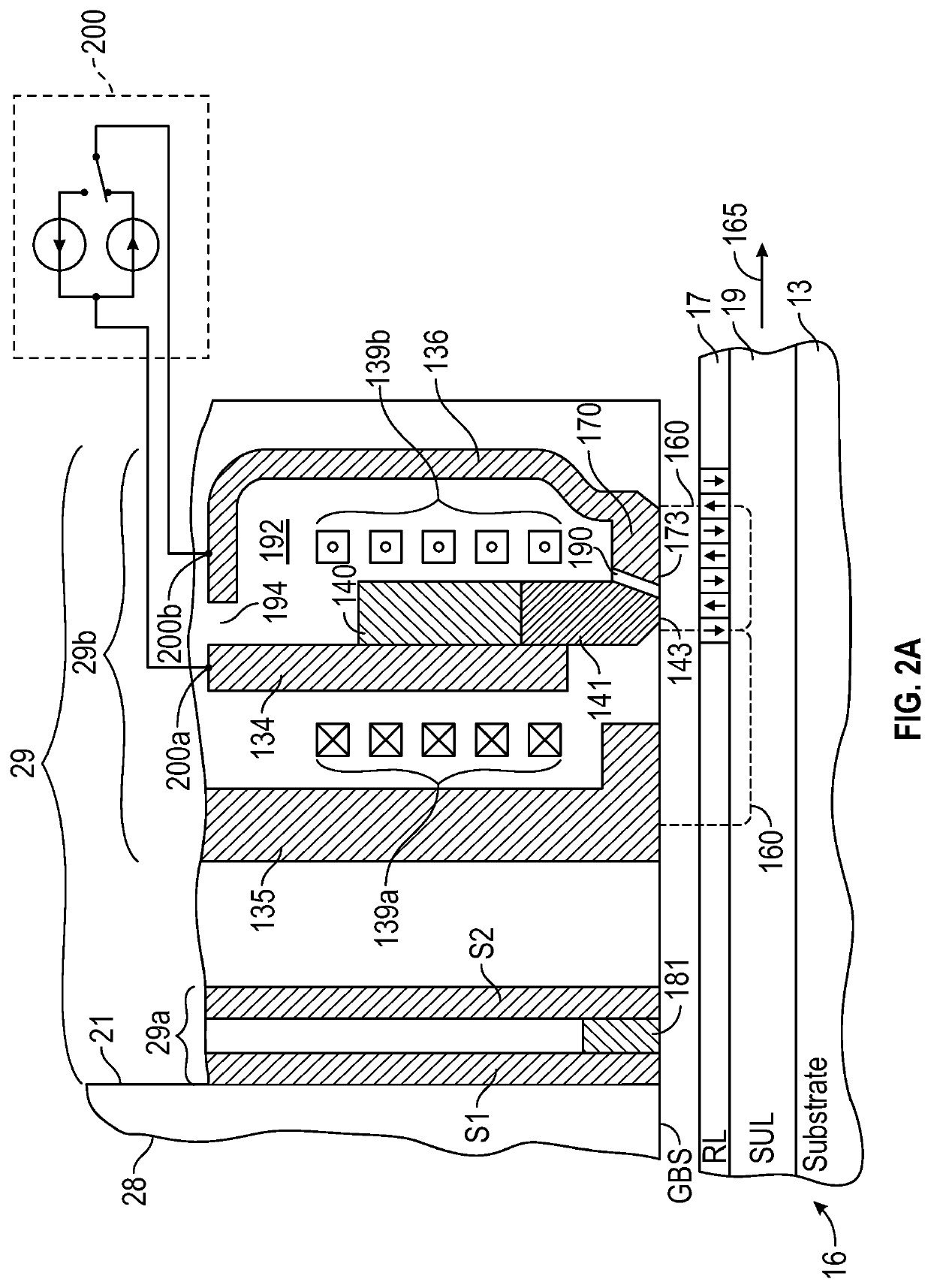
[0024]FIG. 2A is a side sectional view (not to scale) of a perpendicular magnetic recording write head with a non-magnetic electrically-conductive layer 190 incorporated in the write gap, a read head and a recording disk taken through a central plane that intersects a data track on the disk. As shown in FIG. 2A, a “dual-layer” disk 16 includes a perpendicular magnetic data recording layer (RL) 17 on a “soft” or relatively low-coercivity magnetically permeable underlayer (SUL) 19 formed on the disk substrate 13. The read / write head 29 is formed on slider 28 that has a disk-facing or gas-bearing surface (GBS) and includes read head 29a and write head 29b. Read head 29a includes a magnetoresistive (MR) read element or sensor 181 located between two magnetic shields S1, S2. The current-assisted write head 29b is a perpendicular magnetic recording (PMR) write head and includes a yoke structure with main pole 134, write pole 141 with upper portion 140 and disk-facing end 143, optional fir...


PUM


Abstract

A current-assisted magnetic recording write head has an electrically conductive layer in the write gap between the write pole and the trailing shield. Electrical circuitry directs current between the write pole and the trailing shield, through the conductive layer in the write gap. The current through the conductive layer generates an Ampere field substantially orthogonal to the magnetization in the write pole to assist magnetization switching of the write pole. The conductive layer is wider in the cross-track direction than the trailing edge of the write pole and may extend beyond the write pole side gaps so as to be in contact with both the side shields and the trailing shield. The conductive layer may have substantially the same along-the-track thickness across its width or it may have a thicker central region at the write pole trailing edge and thinner side regions.

Description

CROSS-REFERENCE TO RELATED APPLICATIONS[0001]This application claims benefit of U.S. Provisional Patent Application Ser. No. 62 / 686,208, filed Jun. 18, 2019, which is herein incorporated by reference.BACKGROUND[0002]Field of the Invention[0003]This invention relates generally to magnetic recording systems, and more particularly to a magnetic recording system with a current-assisted write head.[0004]Description of the Related Art[0005]Perpendicular magnetic recording (PMR) in magnetic recording hard disk drives, wherein the recorded bits are stored in a perpendicular or out-of-plane orientation in the magnetic recording layer of the disk, allows for ultra-high recording density, i.e., the areal density of the recorded bits on the disk. The write head must be able to write data not only at high bit density but also at high data rates. The write speed is particularly important in enterprise disk drives. However, the time for the main pole of the write head to switch from one magnetizat...

Claims


Application Information

Patent Timeline
IPC IPC(8): G11B5/60G11B5/39
CPCG11B5/3912G11B5/6082G11B5/1278G11B5/1878G11B5/314G11B5/315G11B2005/0005
Inventor ASIF BASHIR, MUHAMMADCHEMBROLU, VENKATESHGONCHAROV, ALEXANDERVAN DER HEIJDEN, PETRUS ANTONIUSCHEN, YINGJIAN
Owner WESTERN DIGITAL TECH INC
Why Eureka
Try Eureka