Exhaust gas aftertreatment system and method for exhaust aftertreatment of an internal combustion engine

a technology of exhaust gas aftertreatment and exhaust gas, which is applied in the direction of exhaust treatment electric control, machines/engines, separation processes, etc., can solve the problems of increased fuel consumption of internal combustion engines, power loss, and impaired running smoothness, and achieve the effect of reducing the temporary emissions breakthrough of exhaust gas components and increasing tailpipe emissions

Active Publication Date: 2021-02-02
VOLKSWAGEN AG
View PDF16 Cites 2 Cited by
  • Summary
  • Abstract
  • Description
  • Claims
  • Application Information

AI Technical Summary

Benefits of technology

[0007]The object of the invention is to ensure that a regeneration temperature of the particle filter is reached in all driving cycles, and to allow preferably emission-free regeneration of the particle filter. Further aims are to improve the aging behavior of the exhaust gas aftertreatment system and to overcome the disadvantages known from the prior art.
[0008]According to the invention, this object is achieved by an exhaust gas aftertreatment system for an internal combustion engine having an exhaust gas system that is connected to an outlet of the internal combustion engine. The exhaust gas system includes an exhaust duct in which a three-way catalytic converter close to the engine as a first emission-reducing component, and downstream from the three-way catalytic converter close to the engine, a four-way catalytic converter or a combination of a particle filter and a second three-way catalytic converter downstream from the particle filter is situated in the flow direction of an exhaust gas of the internal combustion engine through the exhaust duct. The exhaust gas aftertreatment system also includes a secondary air pump and an exhaust gas burner, wherein, downstream from the three-way catalytic converter close to the engine and upstream from the four-way catalytic converter or the particle filter, at least one introduction point is provided at which the hot exhaust gases of the exhaust gas burner are introducible into the exhaust gas system for heating the four-way catalytic converter or the particle filter. In this context, an arrangement of the three-way catalytic converter close to the engine is understood to mean an arrangement of the exhaust aftertreatment components having an exhaust gas path length of less than 80 cm, in particular less than 50 cm, particularly preferably less than 35 cm, starting from an outlet of the internal combustion engine. Accelerated heating of the three-way catalytic converter, in particular after a cold start of the internal combustion engine, is thus possible. Due to the position of the three-way catalytic converter close to the engine, less waste heat is lost through the walls of the exhaust duct, so that the three-way catalytic converter reaches its light-off temperature comparatively early after a cold start of the internal combustion engine. A large quantity of energy may be introduced into the exhaust gas system via the exhaust gas burner, as the result of which the four-way catalytic converter may be heated to its regeneration temperature close in time after a regeneration request. In addition, the exhaust gas burner may be utilized for heating the four-way catalytic converter during a cold start, so that the four-way catalytic converter reaches its light-off temperature close in time after a cold start and thus allows efficient conversion of pollutants. The internal combustion engine is preferably designed as an internal combustion engine that is spark-ignited by means of spark plugs according to the Otto spark ignition principle.

Problems solved by technology

The increase in exhaust back pressure may result in increased fuel consumption by the internal combustion engine, power loss, and impaired running smoothness, even misfiring.
As a result of the good efficiencies in the gasoline engine, regeneration of a particle filter in the underbody position is impossible in certain operating situations, so that special driving cycles are necessary for regenerating a particle filter in the underbody position.
Another problem with three-way catalytic converters having a three-way catalytically active coating, so-called four-way catalytic converters, is the fact that the coating may exhibit severe aging phenomena, so that an additional three-way catalytic converter in a position close to the engine may be necessary for conversion of the gaseous pollutants.

Method used


Image

  • Exhaust gas aftertreatment system and method for exhaust aftertreatment of an internal combustion engine
  • Exhaust gas aftertreatment system and method for exhaust aftertreatment of an internal combustion engine
  • Exhaust gas aftertreatment system and method for exhaust aftertreatment of an internal combustion engine

Examples


Embodiment Construction

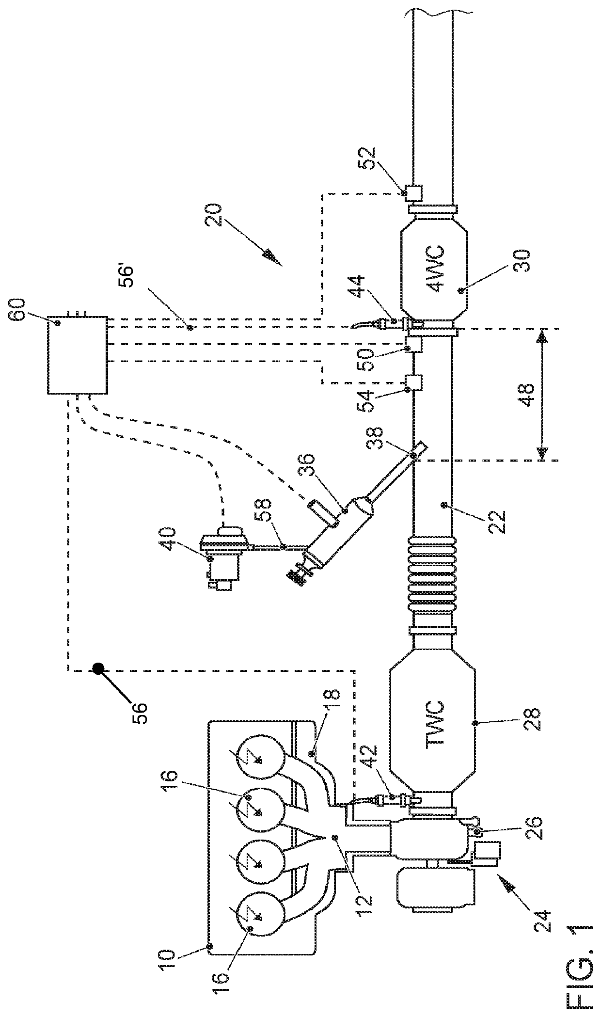
[0036]FIG. 1 shows a schematic illustration of an internal combustion engine 10 whose outlet 12 is connected to an exhaust gas system 20. The internal combustion engine 10 is designed as a gasoline engine that is spark-ignited by means of spark plugs 16, and that has multiple combustion chambers 14. The internal combustion engine 10 is preferably designed as an internal combustion engine 10 that is charged by means of an exhaust gas turbocharger 24, with a turbine 26 of the exhaust gas turbocharger 24 situated downstream from the outlet 12 and upstream from the first emission-reducing exhaust aftertreatment component, in particular upstream from a three-way catalytic converter 28 close to the engine. The exhaust gas system 20 includes an exhaust duct 22 in which a three-way catalytic converter 28 close to the engine is situated in the flow direction of an exhaust gas through the exhaust duct 22, and a four-way catalytic converter 30 is situated downstream from the three-way catalyti...


PUM

PropertyMeasurementUnit
lengthaaaaaaaaaa
lengthaaaaaaaaaa
lengthaaaaaaaaaa

Abstract

The invention relates to an exhaust gas aftertreatment system for an internal combustion engine, in particular for a gasoline engine that is spark-ignited by means of spark plugs. A first three-way catalytic converter is situated in an exhaust gas system that is connected to an outlet of the internal combustion engine in a position close to the engine. Downstream from the first three-way catalytic converter, a four-way catalytic converter or a combination of a particle filter and a second three-way catalytic converter downstream from the particle filter is situated in the underbody position of the motor vehicle. An exhaust gas burner with which hot exhaust gas is introducible into the exhaust gas system downstream from the first three-way catalytic converter and upstream from the four-way catalytic converter or the particle filter is provided at an exhaust duct of the exhaust gas system. The exhaust gas burner is supplied with fresh air by a secondary air pump. The invention further relates to a method for exhaust aftertreatment of an internal combustion engine having such an exhaust gas aftertreatment system.

Description

CROSS-REFERENCE TO RELATED APPLICATIONS[0001]This application claims priority from German Patent Application No. 10 2018 100 240.8, filed Jan. 8, 2018, which is hereby incorporated by reference.FIELD OF THE INVENTION[0002]The invention relates to an exhaust gas aftertreatment system for an internal combustion engine and a method for exhaust aftertreatment of an internal combustion engine according to the preambles of the respective independent claims.BACKGROUND OF THE INVENTION[0003]The increasing stringency of exhaust emission regulations has placed high demands on automotive manufacturers, which are addressed by suitable measures to reduce uncontrolled engine emissions and appropriate exhaust aftertreatment. The EU6 legislation prescribes a particle count limit for gasoline engines, which in many cases requires use of a gasoline engine particle filter. Such soot particles arise in particular after a cold start of the internal combustion engine due to incomplete combustion, in comb...

Claims


Application Information

Patent Timeline
Patent Type & Authority Patents(United States)
IPC IPC(8): F01N3/20F01N3/10F01N3/035F01N3/021F01N13/00F01N3/025F01N3/22B01D46/00B01D53/94F01N3/023F01N3/28
CPCF01N3/2006B01D46/0027B01D46/0063B01D53/9454F01N3/021F01N3/023F01N3/025F01N3/035F01N3/101F01N3/2033F01N3/22F01N3/2892F01N13/008F01N13/009F01N13/0093F01N2240/14F01N2560/025F01N2560/06F01N2560/08F01N2900/1404F01N2900/1602F01N3/32F01N11/007F01N9/002F01N9/00Y02A50/20Y02T10/12F01N11/00B01D46/84
Inventor PAUKNER, STEFANBARON VON CEUMERN-LINDENSTJERNA, FALK-CHRISTIAN
Owner VOLKSWAGEN AG
Why Eureka
Try Eureka