
Apparatus and method for plasma synthesis of carbon nanotubes

a carbon nanotube and plasma synthesis technology, applied in plasma technique, chemical/physical/physical-chemical processes, energy-based chemical/physical/physical-chemical processes, etc., can solve the problems of limiting the scalability of industrial processes, cvd is an inefficient method of obtaining active species for the synthesis of carbon nanotubes, and the structure of tubes is more complicated. , to achieve the effect of facilitating operation and increasing surface area

Active Publication Date: 2021-02-23
LEVIDIAN NANOSYSTEMS LTD
View PDF12 Cites 2 Cited by
  • Summary
  • Abstract
  • Description
  • Claims
  • Application Information

AI Technical Summary

Benefits of technology

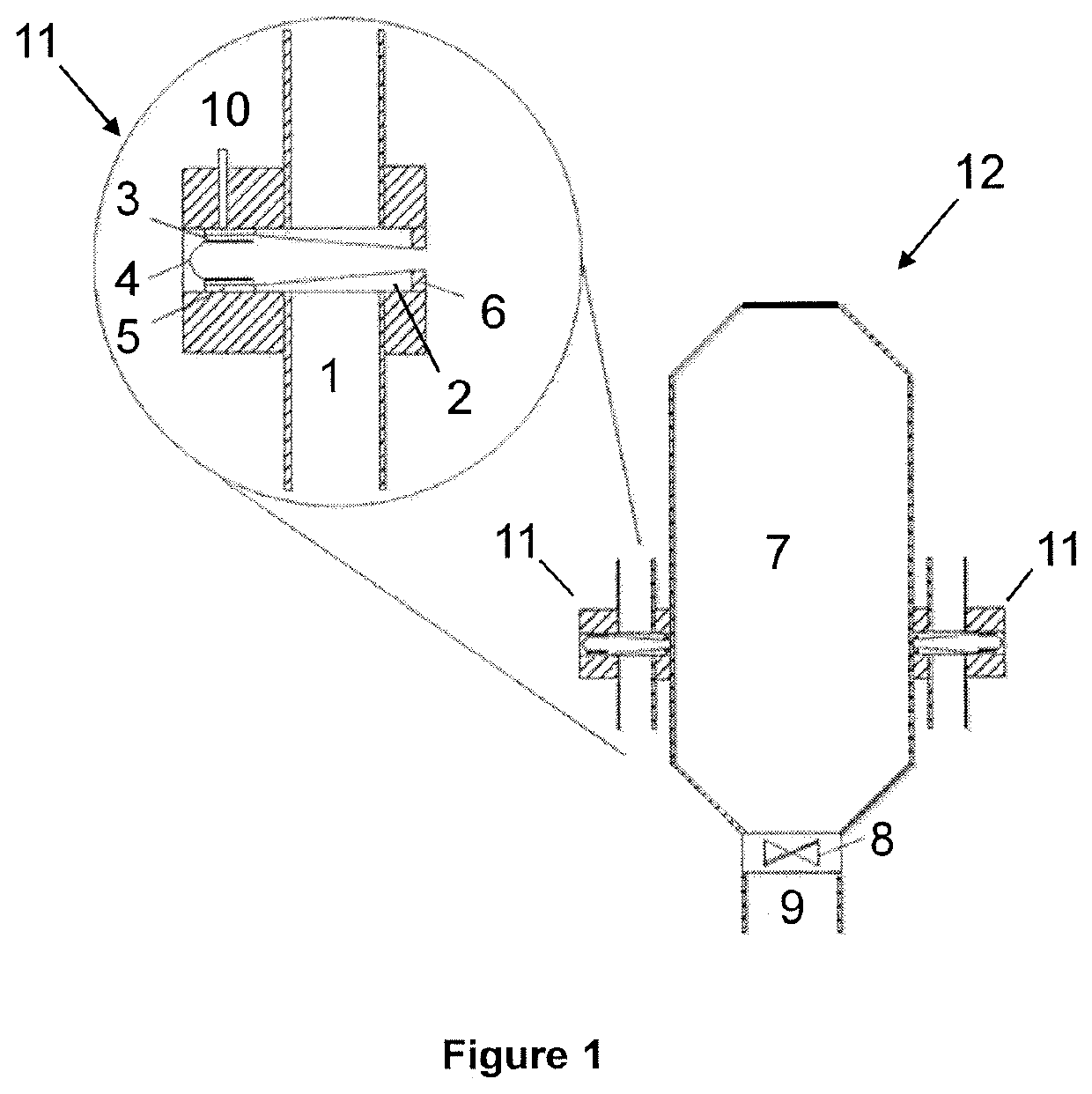
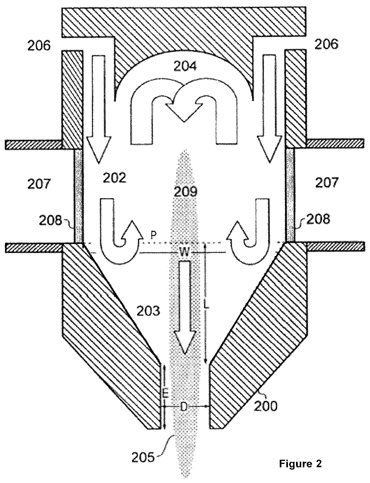
[0017]By virtue of the arrangement of the plasma nozzle such that, in use, an afterglow of the plasma extends into the reaction tube / chamber, the cracked carbon-containing species also pass into the reaction tube / chamber, and the cracked carbon-containing species recombine within the afterglow, this enables CNTs to be produced on a large scale, in some cases in a substrate-free manner.
[0057]The method may further comprise delivering gas around the interface between the or each nozzle and the reaction tube / chamber, so as to maintain sufficient gas flow to minimise carbon deposition.

Problems solved by technology

CVD leads to relatively high yields of CNTs but the tubes show more structural defects than those produced by arc or laser evaporation methods.
However, CVD is an inefficient method of obtaining active species for the synthesis of nanotubes.
Both limit greatly the scalability of the process for industrial purposes.
Low pressure not only requires more sophisticated equipment but also naturally reduces the amount of feedstock that can be provided to the system.
In both cases, the use of substrate or the low power of the plasma torch is still a limiting factor to scale up.

Method used


Image

  • Apparatus and method for plasma synthesis of carbon nanotubes
  • Apparatus and method for plasma synthesis of carbon nanotubes
  • Apparatus and method for plasma synthesis of carbon nanotubes

Examples


examples 1 and 2

[0197]We produced quantities of CNTs in accordance with the present work, by direct injection of the catalyst precursor into the plasma afterglow. The synthesis conditions were as follows:

example 1

[0198]Natural gas was injected into the plasma nozzle at a level of 2 L / min together with hydrogen as a dilution gas at a level of 25 L / min, which results in a natural gas / hydrogen weight ratio in the feedstock of 100. Cracking of the hydrocarbon source at this dilution level leads to CNT formation. CNTs were collected in a filter at the end of a 1.5 m long reaction tube attached to the plasma nozzle.

example 2

[0199]Natural gas was injected into the plasma nozzle at a level of 5 L / min together with hydrogen as a dilution gas at a level of 25 L / min, which results in a natural gas / hydrogen weight ratio in the feedstock of 250. Cracking of the hydrocarbon source at this more concentrated level leads to CNT formation. CNTs were collected in a filter at the end of a 1.5 m long reaction tube attached to the plasma nozzle.

[0200]FIG. 7 presents Raman spectra of the CNTs of Example 1, and FIG. 8 presents Raman spectra of the CNTs of Example 2.

[0201]The relative intensity data of the peaks of the spectra in FIG. 7 are as follows:

[0202]

Infrared (785 nm)Red (633 nm)Green (532 nm)RamanRelativeRamanRelativeRamanRelativeshift (cm−1)intensityshift (cm−1)intensityshift (cm−1)intensity 1490.60464.50.197139.50.106 182.50.225145.50.321167.50.213 205.50.3291920.4761880.096 228.50.4302150.24813380.0331298.20.0471310.50.128159111564.50.3111581.512657.50.2561590.5117280.1041727.50.08426110.28025680.120

[0203]Simi...


PUM

PropertyMeasurementUnit
operating temperatureaaaaaaaaaa

Abstract

Apparatus and method for plasma synthesis of carbon nanotubes couple a plasma nozzle to a reaction tube / chamber. A process gas comprising a carbon-containing species is supplied to the plasma nozzle. Radio frequency radiation is supplied to the process gas within the plasma nozzle, so as to sustain a plasma within the nozzle in use, and thereby cause cracking of the carbon-containing species. The plasma nozzle is arranged such that an afterglow of the plasma extends into the reaction tube / chamber. The cracked carbon-containing species also pass into the reaction tube / chamber. The cracked carbon-containing species recombine within the afterglow, so as to form carbon nanotubes in the presence of a catalyst.

Description

FIELD OF THE INVENTION[0001]The present invention relates to an apparatus and method for plasma synthesis of carbon nanotubes. It is particularly applicable, but by no means limited, to the production of carbon nanotubes using atmospheric pressure microwave plasma.BACKGROUND TO THE INVENTION[0002]Carbon nanotubes, then referred to as ‘tubular fullerenes’, were first observed by lijima in 1991 as ‘micro tubules of graphitic carbon’ [1].[0003]To date, Chemical Vapour Deposition (CVD) is the most commonly used method for synthesizing carbon nanotubes (CNTs), as it is possible to produce a high quantity of CNTs at low cost. During CVD, metal catalyst particles are placed on a substrate which is heated in a reactor at 700-1000° C. A hydrocarbon source (usually gaseous such as e.g. methane or ethylene) is then introduced into the furnace along with a process gas (such as ammonia, nitrogen or hydrogen). During the reaction, the hydrocarbon gases dissociate, producing carbon. Nanotubes then...

Claims


Application Information

Patent Timeline
Patent Type & Authority Patents(United States)
IPC IPC(8): H01J37/32C01B32/162C01B32/164B01J19/12H05H1/30B01J19/08H05H1/46B82Y40/00
CPCH01J37/32229B01J19/088B01J19/126B01J19/129C01B32/162C01B32/164H01J37/32174H01J37/32192H01J37/32311H01J37/32449H01J37/32522H05H1/30H05H1/46B01J2219/0869B01J2219/0875B01J2219/0892B01J2219/0898B82Y40/00H05H2001/4622H05H1/4622C01B32/16H05H1/42
Inventor PAUKNER, CATHARINAKURZEPA, LUKASZKOZIOL, KRZYSZTOF KAZIMIERZ
Owner LEVIDIAN NANOSYSTEMS LTD
Learn More