
R-T-B based permanent magnet

a permanent magnet and rtb technology, applied in the field of rtb based permanent magnets, can solve the problems of insufficient coercivity and squareness ratio, inability to obtain sufficient coercivity, and easy occurrence of abnormal grain growth during sintering. achieve the effect of high coercivity

Active Publication Date: 2021-03-09
TDK CORPARATION
View PDF16 Cites 0 Cited by
  • Summary
  • Abstract
  • Description
  • Claims
  • Application Information

AI Technical Summary

Benefits of technology

[0023](2) A particle size of a finely pulverized powder is reduced so that the main phase grains have an average grain size of 2.8 μm or less, and an abnormal grain growth during sintering is prevented by increasing a Zr content more than before to 0.65 mass % or more.
[0032]The R-T-B based permanent magnet of the present invention makes it possible to obtain a high coercivity even with a composition of reduced contents of Dy and Tb due to combination between an improvement in coercivity by a composition of a reduced B content and an improvement in coercivity by miniaturization of the main phase grains. The present inventors conceive as below the reason why in a specific composition region where a B content is small and a Zr content is large, a value of coercivity varies sensitively due to an amount of carbon contained in the R-T-B based permanent magnet, and a high coercivity can be obtained only at the time of a specific composition balance.
[0047]The present invention makes it possible to provide the R-T-B based permanent magnet capable of obtaining a high coercivity even if a use amount of a heavy rare earth element is reduced.

Problems solved by technology

The following problems, however, have become clear only if those techniques are simply combined.
When the particle size of the finely pulverized powder is miniaturized, however, abnormal grain growth during sintering tends to easily occur as mentioned above.
It was found out, however, that if the sintering temperature is low with a composition of a reduced B concentration, soft magnetic Fe grains become easy to remain in the permanent magnet, and coercivity and squareness ratio cannot be obtained sufficiently.
Thus, when the particle size of the finely pulverized powder was reduced with a composition of a reduced B concentration, a sufficient coercivity could not be obtained due to the remaining of Fe grains under a condition of a low sintering temperature, and a sufficient coercivity could not be obtained due to the abnormal grain growth under a condition of a high sintering temperature.
When an additive amount of Zr is simply increased, however, there is a problem that coercivity decreases significantly and an R-T-B based permanent magnet having a sufficient coercivity cannot be obtained, even though the abnormal grain growth during sintering can be prevented.

Method used


Image

  • R-T-B based permanent magnet
  • R-T-B based permanent magnet

Examples


first embodiment

[0051]The first embodiment of the present invention is directed to an R-T-B based sintered magnet that is a kind of R-T-B based permanent magnets.

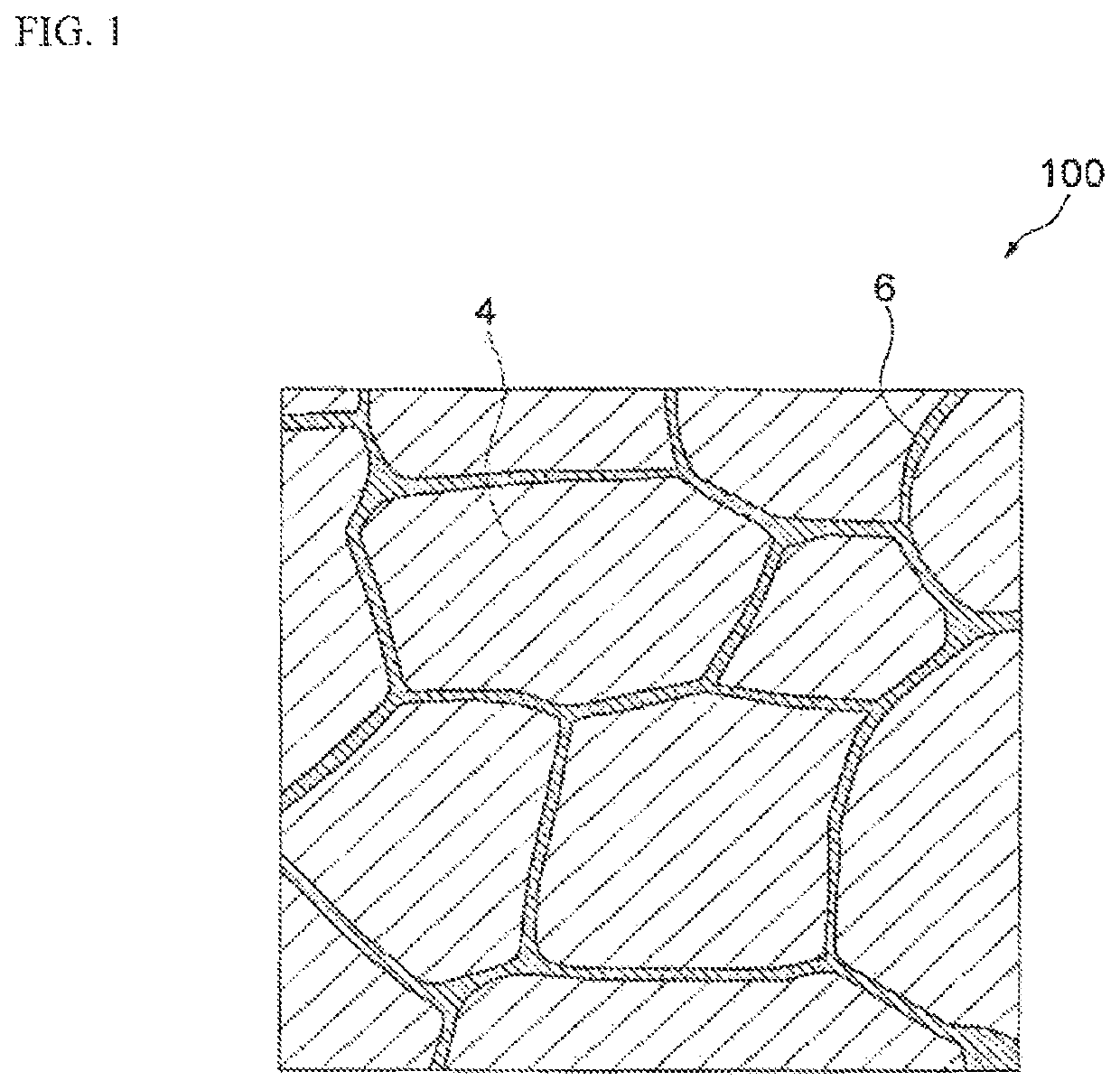
[0052]The R-T-B based sintered magnet according to the first embodiment of the present invention will be described. As shown in FIG. 1, an R-T-B based sintered magnet 100 according to the present embodiment contains main phase grains 4 composed of R2T14B type compound and grain boundaries 6 present among the main phase grains 4.

[0053]The main phase grains contained in the R-T-B based sintered magnet according to the present embodiment are composed of R2T14B type compound having crystal structure of R2T14B type tetragonal.

[0054]R represents at least one kind of rare earth elements. Rare earth elements are Sc, Y, and lanthanoid elements belonging to Group 3 in the long-periodic table. For example, lanthanoid elements include La, Ce, Pr, Nd, Sm, Eu, Gd, Tb, Dy, Ho, Er, Tm, Yb, Lu etc. Rare earth elements are divided into light rare earth elem...

second embodiment

[0107]The second embodiment of the present invention is directed to an R-T-B based permanent magnet manufactured by hot working. Matters of the second embodiment that are not described below are identical to those of the first embodiment. The term of “sintering” in the first embodiment shall be replaced as necessary.

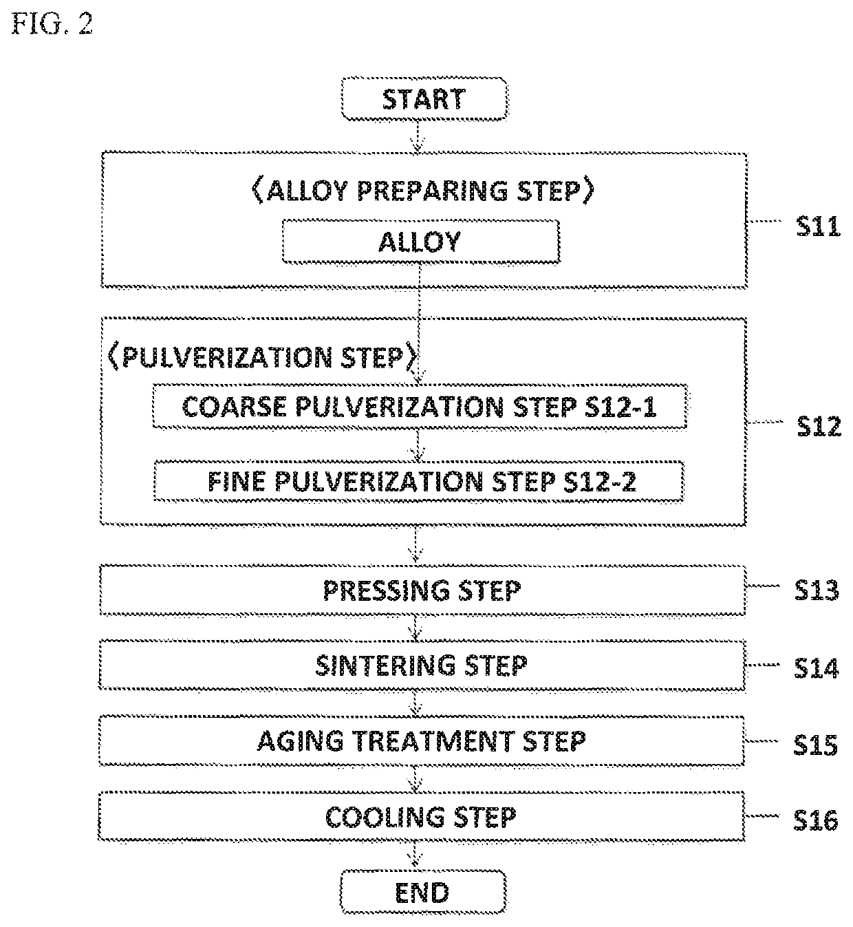
[0108]The method for manufacturing the R-T-B based permanent magnet according to the present embodiment has the following steps.

[0109](a) Melt rapid cooling step for melting a raw material metal and rapidly cooling an obtained molten metal to obtain a ribbon

[0110](b) Pulverization step for pulverizing the ribbon to obtain a flaky raw material powder

[0111](c) Cold forming step for performing cold forming to the pulverized raw material powder

[0112](d) Preliminary heating step for preliminarily heating the cold-formed body

[0113](e) Hot forming step for performing hot forming to the preliminarily heated cold-formed body

[0114](f) Hot plastic working step for plastically defor...

examples

[0138]Hereinafter, the invention will be described in more detail based on the examples, but is not limited thereto.


PUM

PropertyMeasurementUnit
grain sizeaaaaaaaaaa
residual magnetic flux densityaaaaaaaaaa

Abstract

An R-T-B based permanent magnet includes main phase grains composed of R2T14B type compound. R is a rare earth element. T is iron group element(s) essentially including Fe or Fe and Co. B is boron. An average grain size of the main phase grains is 0.8 μm or more and 2.8 μm or less. The R-T-B based permanent magnet contains at least C and Zr in addition to R, T, and B. B is contained at 0.75 mass % or more and 0.88 mass % or less. Zr is contained at 0.65 mass % or more and 5.00 mass % or less. A formula (1) of 5.0≤[B]+[C]−[Zr]≤5.6 is satisfied, where [B] is a B content represented by atom %, [C] is a C content represented by atom %, and [Zr] is a Zr content represented by atom %.

Description

BACKGROUND OF THE INVENTION[0001]1. Field of the Invention[0002]The present invention relates to an R-T-B based permanent magnet whose main components are a rare earth element (R), at least one or more kinds of iron element essentially including Fe or Fe and Co (T), and boron (B).[0003]2. Description of the Related Art[0004]R-T-B based permanent magnets have excellent magnetic properties and are thus used for home electric appliances, various kinds of motors such as voice coil motors (VCM) of hard disk drive and motors mounted on hybrid cars, and the like. When the R-T-B based permanent magnet is used for the motor or so, it is required to be excellent in heat resistance for responding to a use environment of high temperature and further have a high coercivity.[0005]As a method for improving coercivity (HcJ) of the R-T-B based permanent magnet, the rare earth element R to which a light rare earth element of Nd, Pr etc. is mainly applied is partially substituted with a heavy rare ear...

Claims


Application Information

Patent Timeline
Patent Type & Authority Patents(United States)
IPC IPC(8): H01F1/057B22F9/04B22F3/16C22C33/02B22D11/00B22F5/00C21D3/06C22C38/00C22C38/06C22C38/10C22C38/14C22C38/16H01F1/058
CPCH01F1/0577B22D11/001B22F3/16B22F5/00B22F9/04C21D3/06C22C33/0278C22C38/001C22C38/002C22C38/005C22C38/06C22C38/10C22C38/14C22C38/16B22F2009/042B22F2009/044B22F2201/11B22F2201/20B22F2301/355B22F2998/10C22C2202/02H01F1/058H01F7/0273
Inventor MIWA, MASASHIIWASA, TAKUROU
Owner TDK CORPARATION
Learn More