
UV Raman microscope analysis system

a raman microscope and analysis system technology, applied in the field oframan spectroscopy, can solve the problems of not being able to get useful raman signals, unable to get excitation beams focused, and even trace amounts of explosive materials on scanned surfaces, so as to promote effective detection of minute quantities, improve resolution, accuracy, or effectiveness of detection, effect of improving resolution and accuracy

Active Publication Date: 2021-04-06
ALAKAI DEFENSE SYST
View PDF10 Cites 0 Cited by
  • Summary
  • Abstract
  • Description
  • Claims
  • Application Information

AI Technical Summary

Benefits of technology

The present invention provides better methods, systems, and apparatus to solve problems in the art. One advantage is that the approach is based on Raman spectroscopy, which can detect small amounts of substances without destroying or damaging them. Another advantage is that the method can scan irregular surfaces and access larger areas of a sample. Additionally, the invention offers optional enhancement features to improve resolution, accuracy, and detection of very small amounts of substances.

Problems solved by technology

While there are challenges to extracting reliable Raman signal from noise in Raman scattering, it can reveal even trace amounts of explosive material on a scanned surface.
But there can be difficulties in both getting the excitation beam focused on a relevant part of the target, and getting useful Raman signal out of the scattering.
But, as mentioned, this can limit the nature of samples that can be scanned.
This can present significant challenges to not only getting a good Raman signal out of the return but getting an accurate focus of the excitation source on a relevant surface of a distant target.
As such, these competing and sometimes agnostic factors, present challenges and unpredictability when trying to satisfy such competing factors.

Method used


Image

  • UV Raman microscope analysis system
  • UV Raman microscope analysis system
  • UV Raman microscope analysis system

Examples


Embodiment Construction

A. Overview

[0037]For a better understanding of the invention, non-limiting examples of several different forms and embodiments the invention can take will now be described in detail. It is to be understood that these examples are neither exclusive nor inclusive of all forms and embodiments possible with the invention.

[0038]For example, exemplary embodiments discussed below will focus upon detection of explosive such as potassium nitrate (KNO3) as a chemical species of interest. Those skilled in the art understand that the invention can be applied to any number of other chemical species for any number of purposes so long as they can be extracted from Raman scattering. For example, there can be other chemical species of interest to be detected relative to explosives for public, private, security, or military purposes. But there can be non-explosive chemical species of interest that could benefit from aspects of the invention. One example is detection of a pesticide or insecticide on f...


PUM


Abstract

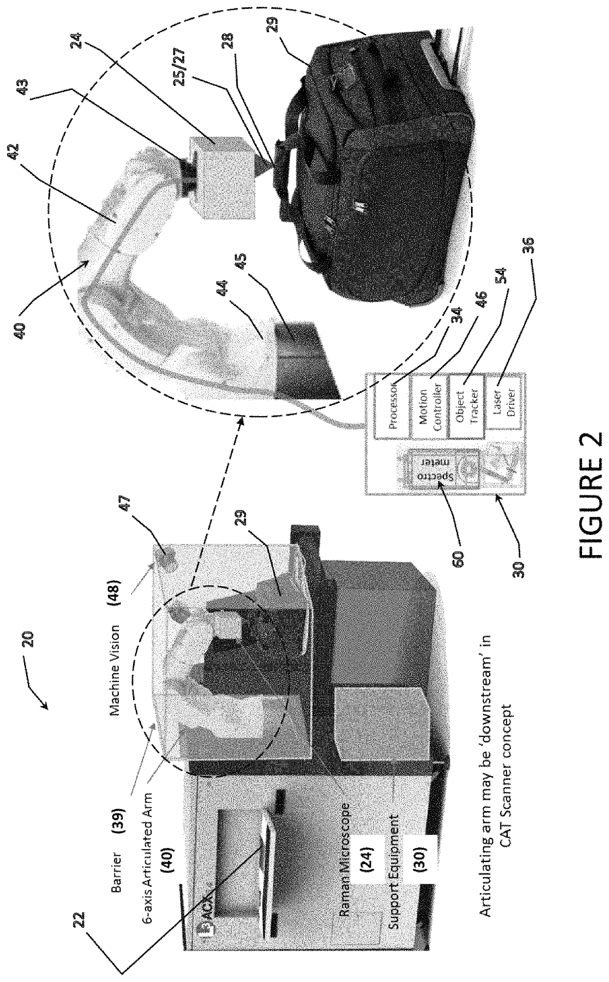
A method and system for interrogating a target for one or more chemical species of interest using Raman microscopy and spectroscopy. A feature includes the ability to precisely electro-mechanically move and orient a Raman microscope relative to the target with multiple degrees of freedom of movement, including targets with 3-D form factors. This promotes effective detection of minute quantities of chemical species of interest. It also allows effective detection of minute quantities whether the target is static or moving. The method and system can include enhancements. Examples include alternative imaging spectrometers, alternative Raman microscope optical set-ups, and alternative focusing techniques. Others include control of the excitation energy and user controls and options to allow highly adjustable, flexible, and effective detection for a variety of detection applications.

Description

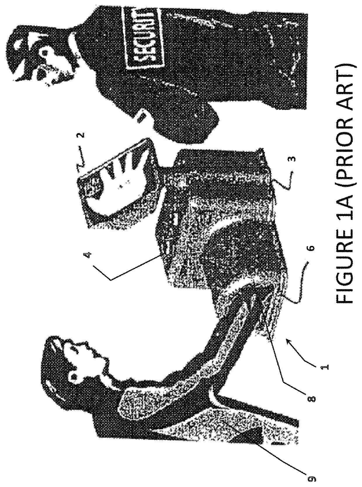
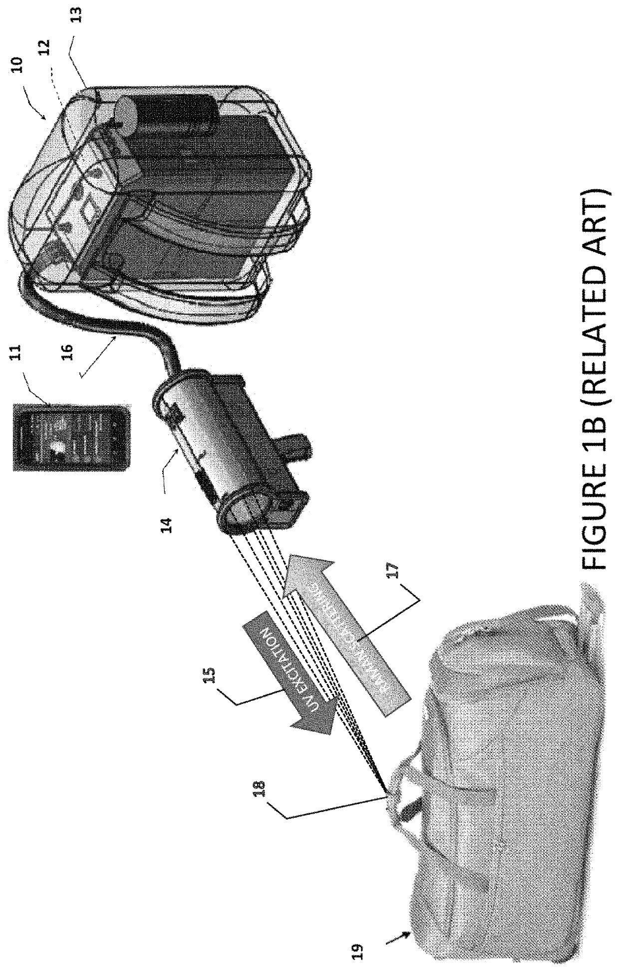
CROSS-REFERENCE TO RELATED APPLICATIONS[0001]This application claims the benefit of Provisional Application U.S. Ser. No. 62 / 833,315 filed on Apr. 12, 2019, all of which is herein incorporated by reference in its entirety.GRANT REFERENCE[0002]Work for this invention was funded in part by grants from the Independent Research and Development (IRAD) & Department of Homeland Security (DHS) under contract #HSHQDC-16-C-B0024. The United States government may have certain rights in this invention.I. BACKGROUND OF THE INVENTIONA. Field of the Invention[0003]The present invention relates to Raman spectroscopy and, in particular, to use of Raman spectroscopy for detection of trace amounts of chemical species on a target.B. Related Art[0004]Raman spectroscopy has proven valuable for detecting chemical species non-destructively and without substantial disruption of a target (e.g. without destructively or otherwise removing a sample from the target object, surface, or area). An electromagnetic e...

Claims


Application Information

Patent Timeline
IPC IPC(8): G01J3/44G01N21/65G01J3/02
CPCG01N21/658G01J3/0248G01J3/44G01J3/0208G01J3/0237G01J3/0289G01J3/2823G01N21/65
Inventor VUNCK, DARIUSWATERBURY, ROBERT DOUGLASMOLNER, TIMOTHYDOTTERY, EDHARDY, HUNTERROBINS, RYANCONGHUYENTONNU, THUYAN
Owner ALAKAI DEFENSE SYST
Learn More