Physically reconfigurable structurally embedded vascular antenna and method of making

a vascular antenna and structural antenna technology, applied in the field of antennas, to achieve the effect of stable radiation behavior, large frequency range, and continuous tunabl

Active Publication Date: 2021-04-20
THE UNITED STATES OF AMERICA AS REPRESETNED BY THE SEC OF THE AIR FORCE
View PDF7 Cites 2 Cited by
  • Summary
  • Abstract
  • Description
  • Claims
  • Application Information

AI Technical Summary

Benefits of technology

[0011]A goal of the present invention is to provide a continuously tunable broadband performance antenna having a large frequency range with stable radiation behavior. A further goal is to provide steering via pattern diversity and / or reconfiguration. The antenna topology chosen to enable both behaviors derives from a length-tunable dipole antenna meandered sinusoidally and antipodally in the lateral (resonant) direction and expanded transversely in a power-series growth envelope. The resulting structure is confined to a geometric region in plane resembling that of a bowtie antenna, but also benefits from the fundamental behavior of a dipole that is controllable using the flow of liquid metal (LM) in the microvascular channel. The meandering is derived from the zig-zag style of wire log periodic antenna; these antennas can provide stable radiation and impedance characteristics across one or more large bandwidths. The characteristic frequency bands are associated with the aperture angle, size, and rate of growth of the repeating cells. The meandering leads to a number of resonance modes and creates a wider tuning range when compared to a simple linear dipole. It also provides a convenient platform for studying non-trivial planar configurations of LM-filled channels.
[0035]This arrangement provides the advantage of a panel that is easy to manufacture, according to known composite-manufacturing techniques, and which provides sufficient strength for the panel's role as a structural element.

Problems solved by technology

Other approaches which uses switches between RF elements cause an induction spike when connecting or disconnecting the circuit which makes them “noisy”.

Method used


Image

  • Physically reconfigurable structurally embedded vascular antenna and method of making
  • Physically reconfigurable structurally embedded vascular antenna and method of making
  • Physically reconfigurable structurally embedded vascular antenna and method of making

Examples


Embodiment Construction

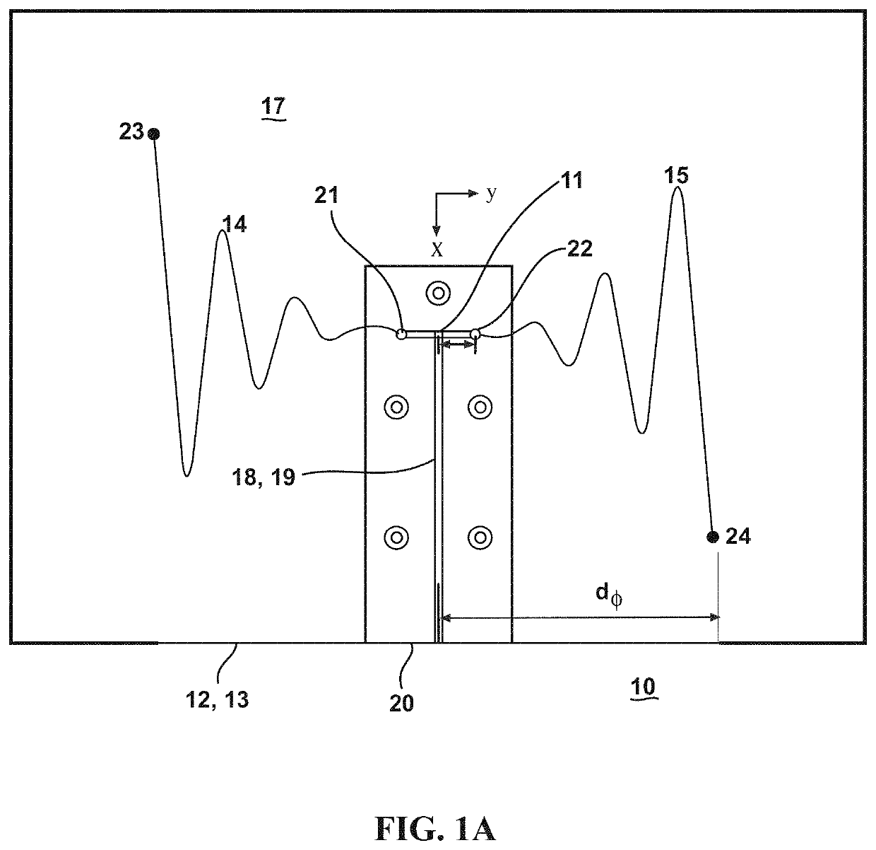
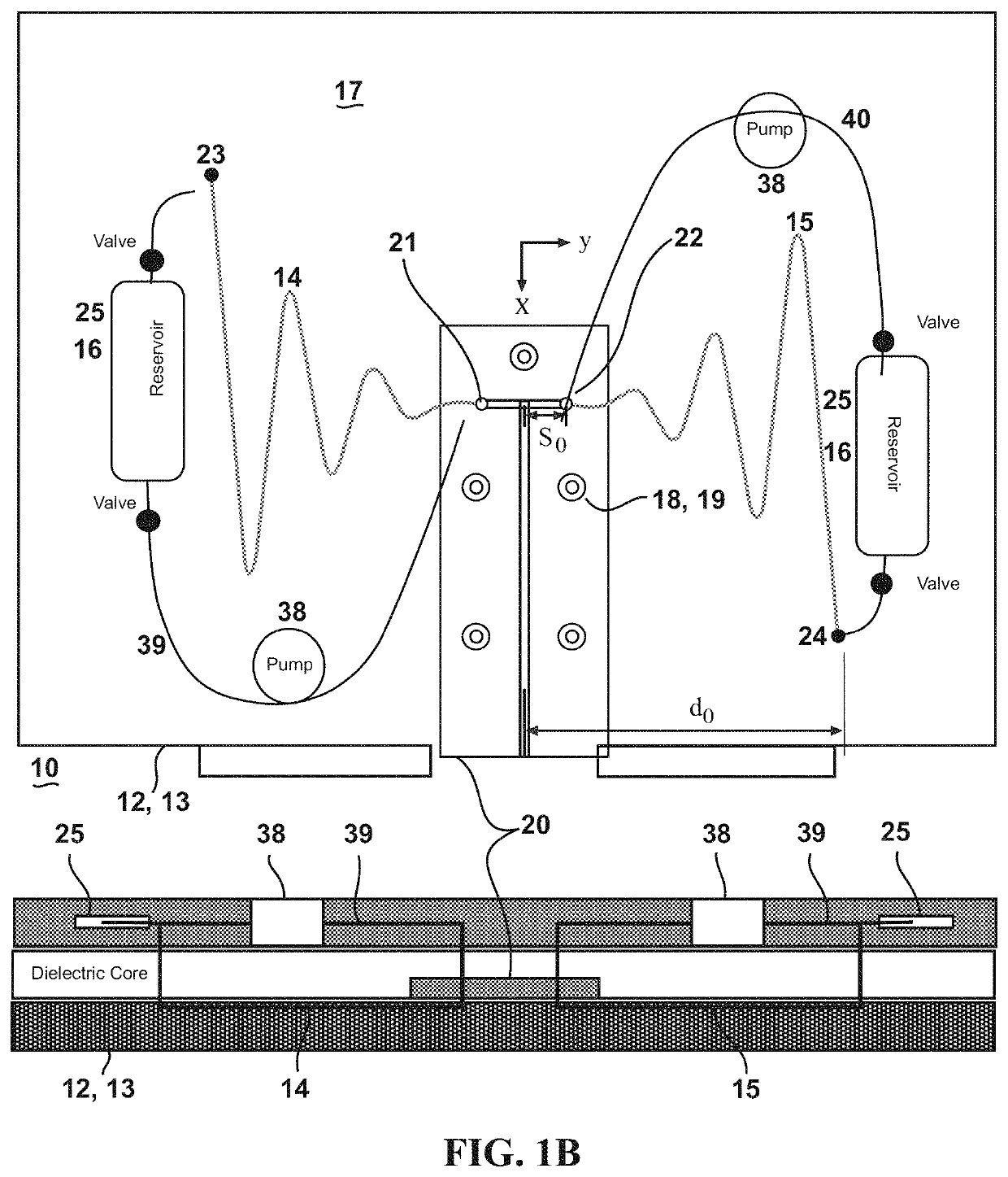
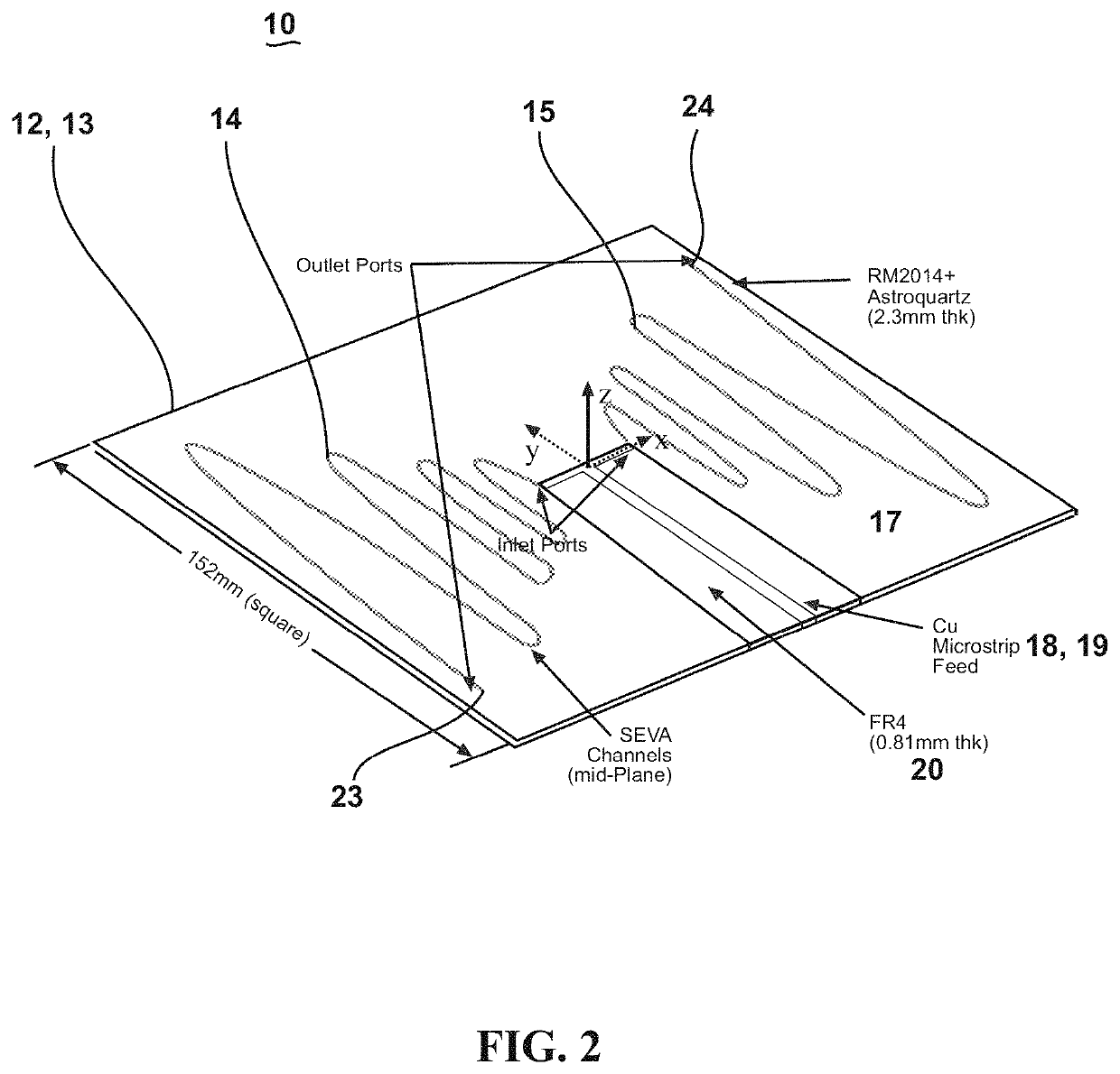
[0064]This invention presents the design, fabrication, and analysis of a “bowtie”-type broadband antenna embedded in a square structural composite panel approximately 6 inches (≈150 mm) in length / width and having radiating elements comprised of liquid metal (LM), these being energized by a custom feed that satisfies both fluid mass and electromagnetic energy transfer goals. EGaIn liquid metal is employed as the reconfigurable electromagnetic fluid. One of the primary advantages of the SEVA concept is the ability to alter antenna transmission or receiving qualities in situ by changing the location or distribution of LM infill into the microvascular network. This permits tuning of resonant frequency and gross adaptation of directivity and gain associated with discrete resonant mode changes as well.

[0065]The following examples illustrate particular properties and advantages of some of the embodiments of the present invention. Furthermore, these are examples of reduction to practice of ...


PUM

PropertyMeasurementUnit
heightaaaaaaaaaa
diameteraaaaaaaaaa
diameteraaaaaaaaaa

Abstract

A method of making a reconfigurable antenna comprises the steps of applying one or more first layers of a prepreg laminate fabric to a form having a desired contour; applying a pattern corresponding to an antenna shape to the first layers of prepreg fabric; applying one or more second layers of the prepreg laminate fabric atop the pattern to form a laminate stack; curing the laminate stack; and removing the pattern to form channels in the antenna shape. The desired contour may be an aircraft skin panel or an airfoil panel. The pattern may be a polymer sheet with an applied cPLA antenna design. The curing step may be performed in a vacuum bag under the application of vacuum and heat. The removing step may be performed by heating the cured laminate stack to remove the pattern.

Description

[0001]Pursuant to 37 C.F.R. § 1.78(a)(4), this application claims the benefit of and priority to prior filed Provisional Application Ser. No. 62 / 472,631, filed 17 Mar. 2017, which is expressly incorporated herein by reference.RIGHTS OF THE GOVERNMENT[0002]The invention described herein may be manufactured and used by or for the Government of the United States for all governmental purposes without the payment of any royalty.FIELD OF THE INVENTION[0003]The present invention relates generally to antennas embedded into structural components and, more particularly, to a physically reconfigurable structurally embedded vascular antenna and methods of making them.BACKGROUND OF THE INVENTION[0004]Broadband antennas are highly advantageous in the field of telecommunications, and some of the most common broadband radiators are spiral, bow-tie, and log periodic antennae. This class of antenna has many geometric variations but it is generally designed so as to maintain radiation characteristics ...

Claims


Application Information

Patent Timeline
Patent Type & Authority Patents(United States)
IPC IPC(8): H01Q1/24H01Q9/28
CPCH01Q1/245H01Q9/28H01Q1/364H01Q3/01H01Q11/105C08K5/5317H01Q9/16H01Q15/002H01Q15/0026H01Q5/30
Inventor BAUR, JEFFERY WHUFF, GREGORY HHARTL, DARREN JFRANK, GEOFFREY JPAN, HONGBRADFORD, ROBYN L
Owner THE UNITED STATES OF AMERICA AS REPRESETNED BY THE SEC OF THE AIR FORCE
Why Eureka
Try Eureka