Method of producing limestone-simulating concrete

a technology of simulating concrete and limestone, which is applied in the field of building materials, can solve the problems that the size of baking soda clumps will also produce significant cavities in the surface, and achieve the effects of reducing the moisture loss rate, minimizing voids, and high solidity

Active Publication Date: 2021-05-11
PEACOCK PAVERS ACQUISITION LLC
View PDF2 Cites 1 Cited by
  • Summary
  • Abstract
  • Description
  • Claims
  • Application Information

AI Technical Summary

Benefits of technology

[0005]The present invention comprises a new process for creating a decorative surface on a cast concrete tile. A mold is prepared by coating with mold release. An aggregate of water, coloring dye, sand, Portland cement, and pea gravel is pre-mixed. Baking soda is mixed with a significant volume of water to create a high-viscosity paste. The paste preferably has a high solid to liquid ratio so that it can be crumbled or molded into baking soda clumps of various sizes. The dampened baking soda clumps are sprinkled randomly onto the bottom surface of the mold (which will bear against what becomes the top surface of the cast tile). The pre-mixed aggregate is then added to the mold. The aggregate is then screed and compressed in the mold to minimize voids. A plastic cover is next added to reduce the moisture loss rate and increase the curing time.
[0007]Once the aggregate is cured, the mold is separated into its component pieces and the cast concrete tile is removed. The residual baking soda is preferably removed. The upper surface of the cast tile will have been etched by the dampened baking soda, producing a variation in color and texture. The size of the baking soda clumps will also produce significant cavities in the surface. The production of the carbon dioxide gas provides a complex texture to the surface of these cavities. The ultimate effect is similar to natural stone.

Problems solved by technology

The size of the baking soda clumps will also produce significant cavities in the surface.

Method used


Image

  • Method of producing limestone-simulating concrete
  • Method of producing limestone-simulating concrete
  • Method of producing limestone-simulating concrete

Examples


Embodiment Construction

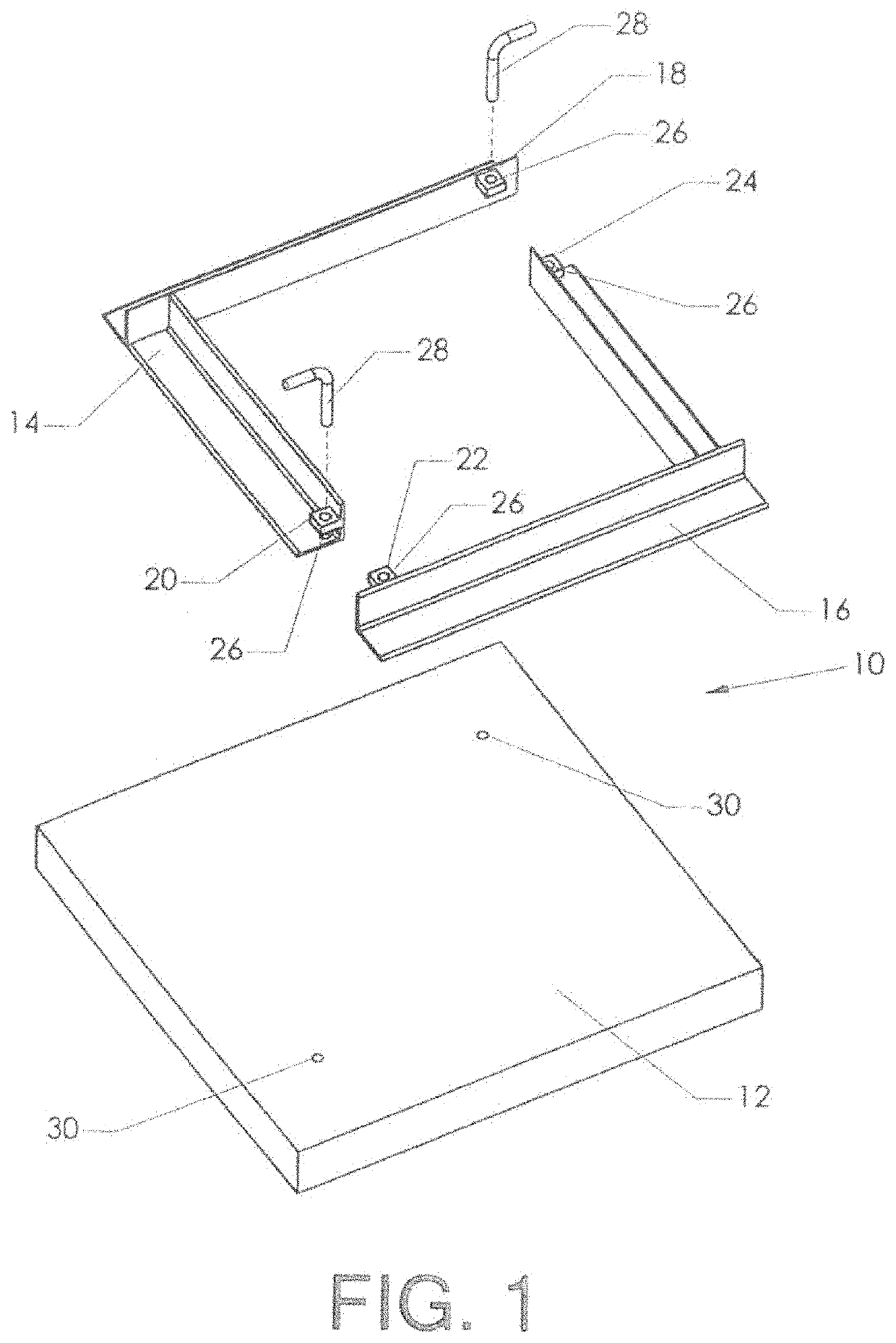
[0063]FIG. 1 shows the components of the mold used to create a cast tile. The mold is created by joining half frame 14 and half frame 16 to base 12. Half frame 14 and half frame 16 are both “L” shaped pieces that form a square when joined at their ends. Half frame 14 has upper tab 18 that mates with lower tab 24 of half frame 16 when the two half frames are joined to form a square. Half frame 14 also has lower tab 20 that mates with upper tab 22 of half frame 16 when the square-framed mold is formed. Corresponding holes 26 of upper tab 18 and lower tab 24 and corresponding holes 26 of upper tab 22 and lower tab 20 align when the two frames are joined and the upper and lower tabs are mated.

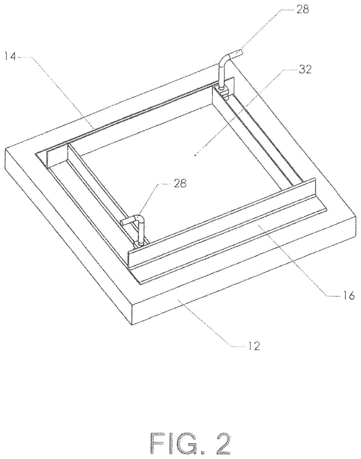
[0064]Base 12 has two pin holes 30 which are adapted to receive pins 28 when tire frame is placed on the base. As described above, corresponding holes 26 of upper tab 18 and lower tab 24 and corresponding holes 26 of upper tab 22 and lower tab 20 are aligned when half frame 14 and half frame 16 are...


PUM

PropertyMeasurementUnit
particle sizeaaaaaaaaaa
sizeaaaaaaaaaa
diameteraaaaaaaaaa

Abstract

A new process for creating a decorative surface on a cast concrete tile. A mold is prepared by coating with mold release. An aggregate of water, coloring dye, sand, Portland cement, and preferably filler material such as pea gravel is pre-mixed. Baking soda is mixed with a significant volume of water to create a high-viscosity paste. The paste preferably has a high solid to liquid ratio so that it can be crumbled into baking soda clumps of various sizes. The dampened baking soda clumps are sprinkled randomly onto the bottom surface of the mold (which will bear against what becomes the top surface of the cast tile). The pre-mixed aggregate is then added to the mold. Once the aggregate is cured, the cast concrete tile is removed. The baking soda clumps create complex voids in the tile's upper surface, producing a surface texture similar to limestone.

Description

CROSS-REFERENCES TO RELATED APPLICATIONS[0001]This application is a continuation-in-part of prior patent application Ser. No. 15 / 010,164. The parent application was filed on Jan. 29, 2016. It listed the same inventors.BACKGROUND OF THE INVENTION1. Field of the Invention[0002]This invention relates to the field of building materials. More specifically, the invention comprises a method for producing a simulated limestone finish on the surface of cast concrete tiles.2. Description of the Related Art[0003]Concrete has been used to cast functional and decorative building materials tor many years. It may be used, as an example, to pour a monolithic floor slab. A finished surface can be created on such a slab, so that no further flooring material is needed.[0004]Concrete is long-lasting and relatively inexpensive. One drawback, however, is its perceived lack of visual appeal. While some recent innovations in decorative surfaces have improved the appeal of concrete, it docs not rival natura...

Claims


Application Information

Patent Timeline
Patent Type & Authority Patents(United States)
IPC IPC(8): B28B7/34B28B1/14B28B7/38C04B14/06C04B28/04C04B38/02C04B40/00C04B40/04C04B20/00C04B28/02B28B7/00C04B111/54C04B103/54
CPCB28B7/38B28B1/14B28B7/007B28B7/342C04B14/06C04B20/0076C04B28/02C04B28/04C04B38/02C04B40/0067C04B40/04B28B2007/005C04B2103/54C04B2111/542
Inventor GORDON, ANN P.GORDON, DONALD R.
Owner PEACOCK PAVERS ACQUISITION LLC
Why Eureka
Try Eureka