Charged particle irradiation apparatus

a technology of irradiation apparatus and charged particles, which is applied in the field of charged particle irradiation apparatus, can solve the problems of tangling or damage, huge apparatus as a whole, and increased storage space for cables

Active Publication Date: 2021-06-01
B DOT MEDICAL INC
View PDF12 Cites 4 Cited by
  • Summary
  • Abstract
  • Description
  • Claims
  • Application Information

AI Technical Summary

Benefits of technology

[0027]a charged particle beam deflected at a deflection angle ϕ relative to the X-axis at a deflection point Q and entering the effective magnetic field region is deflected by the effective magnetic field region and is emitted to the isocenter at an irradiation angle θ relative to the X-axis through the irradiation nozzle,
[0028]an arbitrary point P2 on a boundary defining the effective magnetic field region and located on an exit side of a charged particle beam is located at an equal distance r1 from the isocenter,
[0029]the point P2 and a point P1 on a boundary defining the effective magnetic field region and located on an incident side of a charged particle beam are on an arc of a circle of a radius r2 and a central angle (θ+ϕ), and

Problems solved by technology

When several tens to several hundreds of these thick cables are bundled and used, there is a problem of an increased storage space for the cables.
Further, since a rotating gantry rotates by the maximum of around 180 degrees clockwise or anticlockwise, cables are required to be rotated together, and there is a problem of tangling or damage such as friction between the cables due to rotation.
However, since a cable such as a cabtyre cable has a significantly thick sheath portion, a large bend radius is needed, and this leads to a problem of a huge apparatus as a whole.
Further, when such large and thick cables are located at a position in a sight of a patient and the moving cables can be seen by the patient under treatment, this may give the patient mental pressure or anxiety.

Method used


Image

  • Charged particle irradiation apparatus
  • Charged particle irradiation apparatus
  • Charged particle irradiation apparatus

Examples


Embodiment Construction

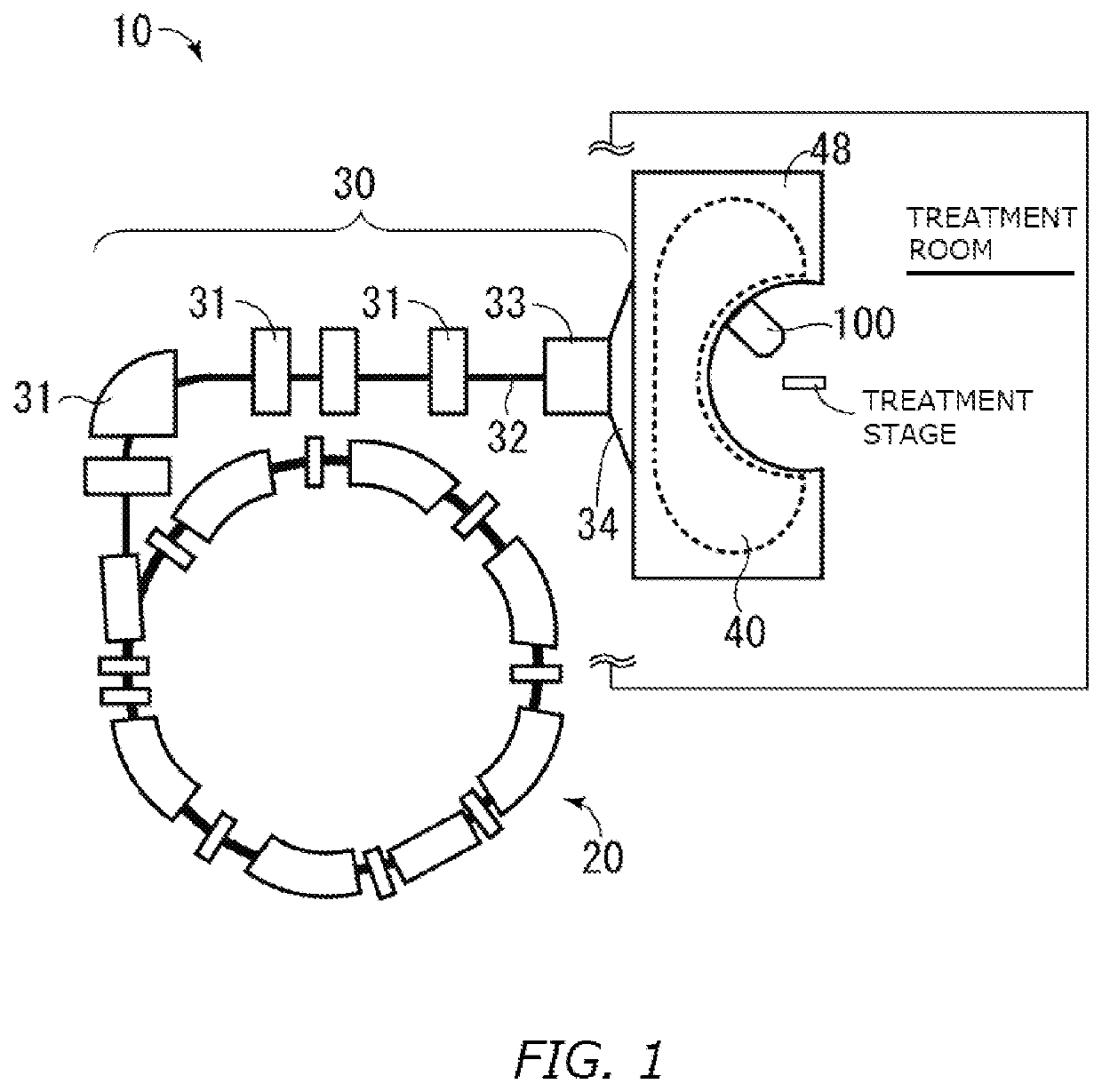
[0045]One embodiment of the present invention relates to a charged particle irradiation apparatus 10 including an irradiation nozzle that continuously moves along the shape on the exit side of an effective magnetic field region of a focusing magnet and irradiates an isocenter with a charged particle beam (also referred to as a particle ray) and a power supply system that supplies power to the irradiation nozzle.

Charged Particle Irradiation Apparatus 10

[0046]FIG. 1 is a schematic diagram of a configuration of the charged particle irradiation apparatus 10 according to one embodiment of the present invention. The charged particle irradiation apparatus 10 has a focusing magnet 40 and an irradiation nozzle 100. The charged particle irradiation apparatus 10 may further have an accelerator 20 and a charged particle beam transport system 30. The irradiation nozzle 100 is arranged inside a treatment room provided with a treatment stage on which a patient is placed.

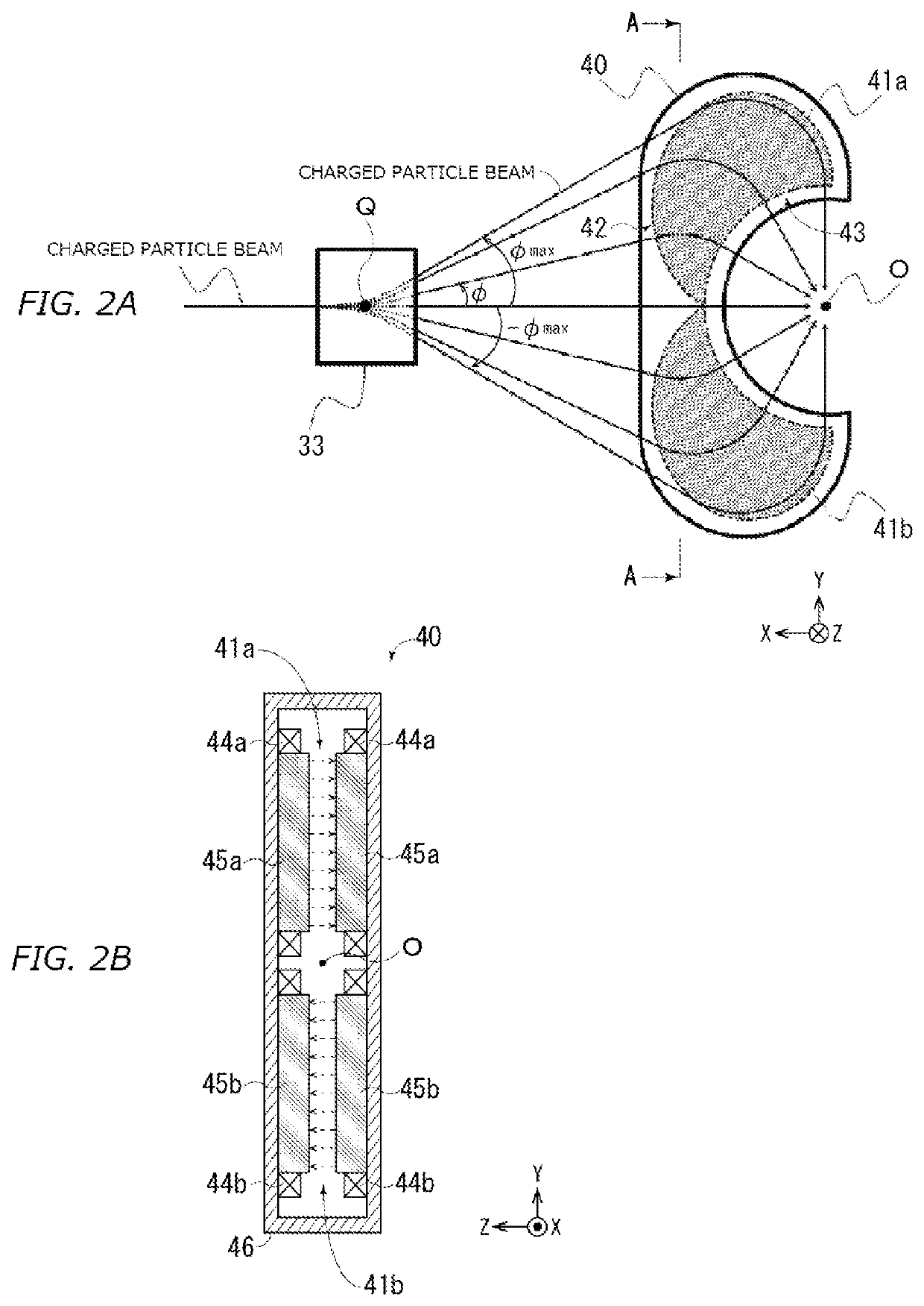
[0047]The focusing magnet 4...


PUM


Abstract

The invention provides a charged particle irradiation apparatus including: a focusing magnet that deflects a charged particle beam to continuously change an irradiation angle of the beam to an isocenter; an irradiation nozzle that continuously moves along a shape on an exit side of an effective magnetic field region of the focusing magnet, wherein the beam exiting the focusing magnet is emitted to the isocenter through the irradiation nozzle; a power supply rail along the shape on the exit side of the region; and a collector shoe fixed to the irradiation nozzle and configured to slide along the rail to supply power from the rail to the irradiation nozzle. A surface of the collector shoe contacted with the rail has the same bend radius as or average bend radius of the rail, and/or the collector shoe slides along the rail in contact with a flat side surface of the rail.

Description

BACKGROUND OF THE INVENTIONField of the Invention[0001]The present invention relates to a charged particle irradiation apparatus.Description of the Related Art[0002]Conventionally, particle therapy treatment to irradiate a malignant tumor such as a cancer with a charged particle beam accelerated by high energy and treat the malignant tumor has been employed.[0003]In particle therapy treatment, a scanning irradiation method for scanning a side direction with a thin charged particle beam extracted from an accelerator by using a scanning magnet, further, dividing a lesion into respective layers in the beam traveling direction, and enabling three-dimensional irradiation has been employed. To transport the charged particle beam extracted from the charged particle accelerator to an irradiation target inside a treatment room, a beam transport system including a bending magnet, a focusing magnet, or the like is used, and the beam transport system has an irradiation nozzle having a scan magn...

Claims


Application Information

Patent Timeline
Patent Type & Authority Patents(United States)
IPC IPC(8): H05H7/04G21K1/06A61N5/10
CPCH05H7/04A61N5/1078G21K1/065A61N2005/1087H05H2007/043H05H2007/045A61N5/1001H05H7/001A61N2005/1085H05H2007/005H05H2007/048H05H2007/002A61N5/1077A61N5/1081A61N5/10G21K5/04G21K1/093A61N5/1065H05H7/22A61N2005/1074
Inventor FURUKAWA, TAKUJIHARA, YOUSUKE
Owner B DOT MEDICAL INC
Why Eureka
Try Eureka