Plastic optical fiber, plastic optical fiber cable, connector-attached plastic optical fiber cable, optical communication system, and plastic optical fiber sensor

a technology of plastic optical fiber and connector, which is applied in the direction of cladded optical fibre, instruments, optical elements, etc., can solve the problems of increasing bending loss and difficult bending, and achieve the effects of reducing transmission loss, reducing bending loss, and reducing connection loss

Active Publication Date: 2021-07-06
ASAHI KASEI KK
View PDF35 Cites 0 Cited by
  • Summary
  • Abstract
  • Description
  • Claims
  • Application Information

AI Technical Summary

Benefits of technology

[0036]According to the present invention, it is possible to provide a plastic optical fiber that simultaneously satisfies a reduction in bending loss, a reduction in connection loss, and a reduction in transmission loss.

Problems solved by technology

On the other hand, however, the bending loss increases, and particularly when the material is quartz or glass, even bending is difficult.

Method used


Image

  • Plastic optical fiber, plastic optical fiber cable, connector-attached plastic optical fiber cable, optical communication system, and plastic optical fiber sensor
  • Plastic optical fiber, plastic optical fiber cable, connector-attached plastic optical fiber cable, optical communication system, and plastic optical fiber sensor
  • Plastic optical fiber, plastic optical fiber cable, connector-attached plastic optical fiber cable, optical communication system, and plastic optical fiber sensor

Examples


example 1

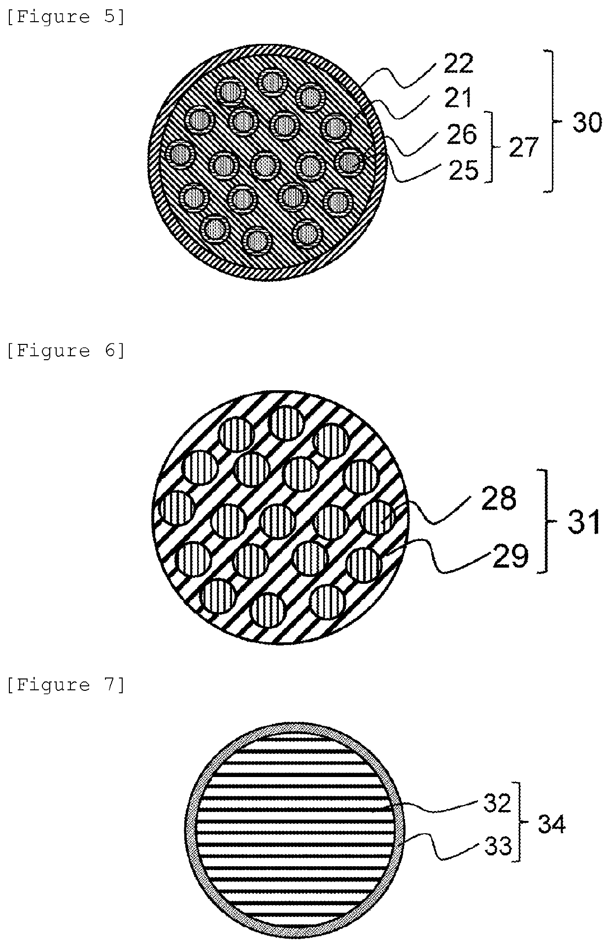
[0099]Polymethyl methacrylate (refractive index 1.491) as a material constituting a first core and second cores, and a copolymer of vinylidene fluoride, tetrafluoroethylene, and hexafluoropropene (refractive index 1.37) as a material constituting a first cladding and second claddings were respectively placed in the core resin distribution chamber and cladding resin distribution chamber of a 1-sea-19-island composite spinning die so that the flow rate ratio was core / cladding=90 / 10, and a 1-sea-19-island plastic optical bare fiber having a diameter of 1 mm was manufactured by composite spinning. The manufactured plastic optical bare fiber was coated (coating diameter 2.2 mm) with polyethylene (SUNTEC-LD M1920 manufactured by Asahi Kasei Corporation) to provide a plastic optical fiber cable. When a cross section was observed by a digital microscope (VHX-5000 manufactured by KEYENCE CORPORATION), it was confirmed that the second claddings were formed in all 19 first island portions, and...

example 2

[0100]A 1-sea-19-island plastic optical fiber cable having a diameter of 1 mm was manufactured as in Example 1 except that a fluorinated methacrylate-based polymer was used as the first cladding and the second claddings. When a cross section was observed as in Example 1, it was confirmed that the second claddings were formed in all 19 first island portions, and the first core that was a sea portion, and the second cores present in the interior of the first island portions both guided light. The plastic optical fiber cable had the structure shown in the schematic cross-sectional view of FIG. 5. The transmission loss was 148 dB / km, which was acceptable. The bending loss was 0.3 dB, which was acceptable. The connection loss was 0.9 dB, which was acceptable. The refractive index of the claddings was lower than the refractive index of the cores.

example 3

[0101]A 1-sea-19-island plastic optical fiber cable having a diameter of 1 mm was manufactured as in Example 1 except that a copolymer of ethylene, tetrafluoroethylene, and hexafluoropropene was used as the first cladding and the second claddings. When a cross section was observed, it was confirmed that the second claddings were formed in all 19 first island portions, and the first core that was a sea portion, and the second cores present in the interior of the island portions both guided light. The plastic optical fiber cable had the structure shown in the schematic cross-sectional view of FIG. 5. The transmission loss was 161 dB / km, which was acceptable. The bending loss was 0.3 dB, which was acceptable. The connection loss was 1.1 dB, which was acceptable. The refractive index of the claddings was lower than the refractive index of the cores.


PUM

PropertyMeasurementUnit
lengthaaaaaaaaaa
refractive indexaaaaaaaaaa
melt flow rateaaaaaaaaaa

Abstract

A plastic optical fiber including a first cladding; a first core forming a first sea portion inside the first cladding; and a first island portion formed inside the first core with at least an outer periphery having a lower refractive index than the first sea portion, wherein the first core includes a polymethyl methacrylate-based resin.

Description

TECHNICAL FIELD[0001]The present invention relates to a plastic optical fiber, a plastic optical fiber cable, a connector-attached plastic optical fiber cable, an optical communication system, and a plastic optical fiber sensor.BACKGROUND ART[0002]A step index type optical fiber is a medium that has a structure in which the periphery of a core comprising a transparent body is surrounded by a cladding comprising a solid having a lower refractive index than that of the transparent body, and transmits light in the core by the reflection of light at the boundary between the core and the cladding (for example, Patent Literature 1). Step index type optical fibers are classified by their materials into quartz glass optical fibers, multicomponent glass optical fibers, polymer-clad silica fibers, plastic optical fibers, and the like and classified by structure into single-core fibers having one core, and multicore fibers in which a plurality of cores are present. Step index type optical fibe...

Claims


Application Information

Patent Timeline
Patent Type & Authority Patents(United States)
IPC IPC(8): G02B1/04G02B6/02
CPCG02B1/046G02B1/048G02B6/02042G02B6/02038G02B6/02319G02B6/02G02B6/02338G02B6/36G02B6/023
Inventor OKITA, KOSHI
Owner ASAHI KASEI KK
Why Eureka
Try Eureka