Microstructure fiber optical parametric oscillator

a microstructure fiber and optical parametric oscillator technology, applied in the direction of optical waveguide light guide, light demodulation, instruments, etc., can solve the problems of undesirable phase sensitive operation of this system, inability to achieve a desired frequency, and the parametric oscillator needs a powerful source and extremely long lengths of fibers to achieve the effect of reducing bending loss

Inactive Publication Date: 2005-10-25
NORTHWESTERN UNIV
View PDF3 Cites 14 Cited by
  • Summary
  • Abstract
  • Description
  • Claims
  • Application Information

AI Technical Summary

Benefits of technology

[0008]In accordance with the present invention, the disadvantages of prior fiber optic parametric oscillators have been overcome. The fiber optical parametric oscillator of the present invention utilizes photonic crystal fibers, also known as holey fibers or microstructure fibers to perform all optical processing functions. By taking advantage of the properties of these types of fibers hereinafter referred to as microstructure fibers, the parametric oscillator of the present invention operates up to thirty times more efficiently than prior devices. The optical parametric oscillator of the present invention requires only a small amount of fiber, and the reduction in bending loss will allow the system to be packaged into a small volume. Further, the ellipticity of the fiber's polarization modes allows the device to be implemented in a relatively simple Fabry-Perot configuration.

Problems solved by technology

The operation of this system, however, is undesirably phase sensitive because all three of the waves are resonant.
They are therefore, not tunable to a desired frequency over the gain bandwidth.
However, this parametric oscillator needs a powerful source and extremely long lengths of fiber.
This scheme, however, suffers from reduction of the power spectral density as the wavelength detuning between the desired signal and the pump is increased.
Furthermore, it has been shown that the coherence of the generated supercontinuum is limited; it leads to progressive degradation of the spectral modulation depth of the signal pulses as one moves away from the pump wavelength.

Method used


Image

  • Microstructure fiber optical parametric oscillator
  • Microstructure fiber optical parametric oscillator
  • Microstructure fiber optical parametric oscillator

Examples


Embodiment Construction

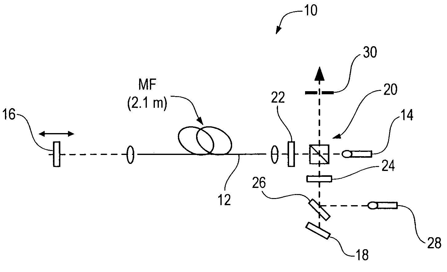
[0024]An optical parametric oscillator 10 in accordance with one embodiment of the present invention, as shown in FIG. 1 utilizes a microstructure fiber 12 also known as a photonic crystal fiber or a holey fiber. The ellipticity of the microstructure fibers polarization modes allows the optical parametric oscillator 10 to be implemented in a relatively simple Fabry-Perot configuration. Moreover, spectral peaks due to cascaded-mixing processes may extend the tunability range of existing high-power lasers.

[0025]One aspect of the present invention is to provide a tunable source in the blue-green region of the spectrum. Heretofore, optical parametric oscillators based on x2 nonlinearities have been used to build tunable sources. However, generating radiation in the blue-green portion of the spectrum requires multiple nonlinear interactions such as second harmonic generation in conjunction with parametric downconversion. Moreover, these optical parametric oscillators require hundreds of ...


PUM

PropertyMeasurementUnit
wavelengthsaaaaaaaaaa
zero dispersion wavelengthsaaaaaaaaaa
zero-dispersion wavelengthaaaaaaaaaa

Abstract

A fiber optical parametric oscillator is formed using photonic crystal fibers, also known as microstructure fibers or holey fibers. The optical parametric oscillator includes only a few meters of microstructure fiber. In one embodiment, the microstructure fiber is disposed between a highly reflective mirror and a diffraction grating in a simple Fabry-Perot configuration wherein the diffraction grating is tuned to reflect a particular wavelength of the signal wave back to the microstructure fiber. In another embodiment, the microstructure fiber is disposed in a ring cavity and the parametric oscillator is synchronously pumped. The parametric oscillator may be implemented with free space optics or use all fiber optic components.

Description

CROSS-REFERENCE TO RELATED APPLICATIONS[0001]This application is a continuation-in-part of U.S. Provisional Application Ser. No. 60 / 414,431 filed Sep. 27, 2002.REGARDING FEDERALLY SPONSORED RESEARCH OR DEVELOPMENT[0002]This work was supported in part by the U.S. Army Research Office under a collaborative MURI grant (DAAD19-00-1-0177) and the associated MURI Fellowship (DAAD19-00-1-0469) as well as by the National Science Foundation under Grants ANI-0123495, ECS-0000241 and the IGERT DGE-9987577.FIELD OF THE INVENTION[0003]The present invention relates to an optical parametric oscillator and more particularly to an optical parametric oscillator utilizing photonic crystal fibers, also known as holey fibers or microstructure fibers.BACKGROUND OF THE INVENTION[0004]Many applications, particularly in the field of wavelength-division-multiplexing (WDM) communication systems, require wavelength-tunable optical pulse sources with multigigahertz repetition rate.[0005]Fiber optical parametric...

Claims


Application Information

Patent Timeline
Patent Type & Authority Patents(United States)
IPC IPC(8): G02F1/39G02F1/35G02B6/02
CPCG02F1/395G02B6/02314G02F2202/32
Inventor KUMAR, PREMSHARPING, JAY E.
Owner NORTHWESTERN UNIV
Why Eureka
Try Eureka