Automated assembly cell and assembly line for producing sand molds for foundries

a technology of sand molds and assembly lines, applied in the field of foundries and casting operations, can solve the problems of large number of robots, stop the whole assembly line, and do not use robots to automatically assemble complex geometry molds with simultaneous assistance of robots, so as to achieve the effect of reducing capital and operating costs and high efficiency

Active Publication Date: 2021-07-20
NEMAK S A B DE
View PDF7 Cites 0 Cited by
  • Summary
  • Abstract
  • Description
  • Claims
  • Application Information

AI Technical Summary

Benefits of technology

[0016]It is therefore an object of the invention to provide an apparatus and method for manufacturing sand mold packages for casting complex-geometry castings with higher efficiency and lower capital and operating costs.
[0017]It is another object of the invention to provide a sand core mold package assembly cell for foundries with higher flexibility which can be used for any design of the casting piece with lower setting up costs and time.
[0019]The objects of the invention are generally achieved by providing a mold package assembly cell comprising a turntable having at least three work spots for holding sand core packages being assembled and at least one robot that places sand cores in a pre-programmed sequence in the corresponding positions in said mold package; characterized by said turntable being capable of rotating about a central axis to position said mold package at different stages of assembly in at least three assembly stations and having at least one robot for manipulating the sand cores and setting said sand cores in their defined places within the mold package. The rotating table has such a shape including at least one recess around its periphery to allow said at least one robot to reach the locations in the mold package where the cores are set to build said mold package. For added flexibility regarding the programmed sequence of setting cores, the rotary table may rotate both clockwise and counterclockwise. In another aspect of the invention, a plurality of mold package assembly cells form an assembly line providing synergistic advantages to produce mold packages of different design and / or to increase the productivity of a mold package manufacturing operation by passing partially assembled mold packages from one cell to another cell of the line when a cell presents operational problems or is shut down for maintenance.

Problems solved by technology

The currently-used mold assembly lines based on use of conveyors present a number of disadvantages during formation of the mold package.
For example, if one of the robots presents a failure, or the supply of one of the cores is delayed or interrupted, the whole assembly line stops.
Since the cores assembling operation has a predetermined sequence there is no way to advance some of the incomplete packages to the next assembly stations by-passing the non-working station.
The layout of the conveyor-based assembly lines need a large area in the foundry and must produce only one mold design per product run without any flexibility for simultaneously assembling mold packages of different designs.
Another drawback of the conveyor-based assembly lines is that a large number of robots are required because the moving path of the mold packages is linear and so only two robots may be placed at each assembly station.
This patent however does not use robots for automatically assembling complex geometry molds with simultaneous assistance of robots.
This patent however does not teach or suggest the use of robots for an automatic operation.
This core assembling system does not provide the flexibility for simultaneously and automatically assembling several cores in the mold.
This system does not provide the productivity of the invention wherein the robots surround a turntable shaped to better accommodate the robots with a unique layout and that permits the robots to operate simultaneously in several work stations.
The system of this patent has a number of disadvantages, such as requiring a large number of robots.
Also, since the mold packages are assembled following a single linear path, there is no possibility of returning the molds to prior assembly positions, and there is no teaching or suggestion about arranging several assembly units to form a mold assembly line.
This mold assembly unit does not provide the flexibility to continue assembly of the molds, even if the conveyor has to be shut down for any mechanical problem or for maintenance.

Method used


Image

  • Automated assembly cell and assembly line for producing sand molds for foundries
  • Automated assembly cell and assembly line for producing sand molds for foundries
  • Automated assembly cell and assembly line for producing sand molds for foundries

Examples


Embodiment Construction

[0024]Manufacturing of sand mold packages for mass production of automotive or aviation light-metal cast parts of complex geometry, such as engine blocks and heads, under the constraints of high productivity and precision requires the coordination of machine tools and human operators to produce the multiple cores forming the mold cavity for casting said parts.

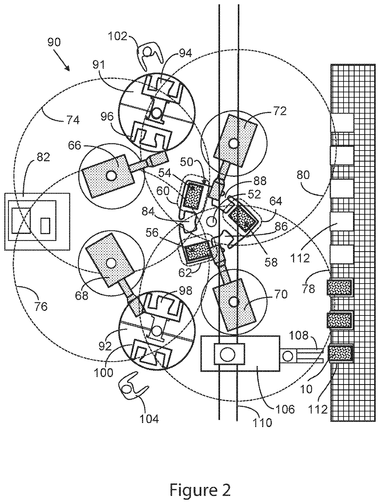
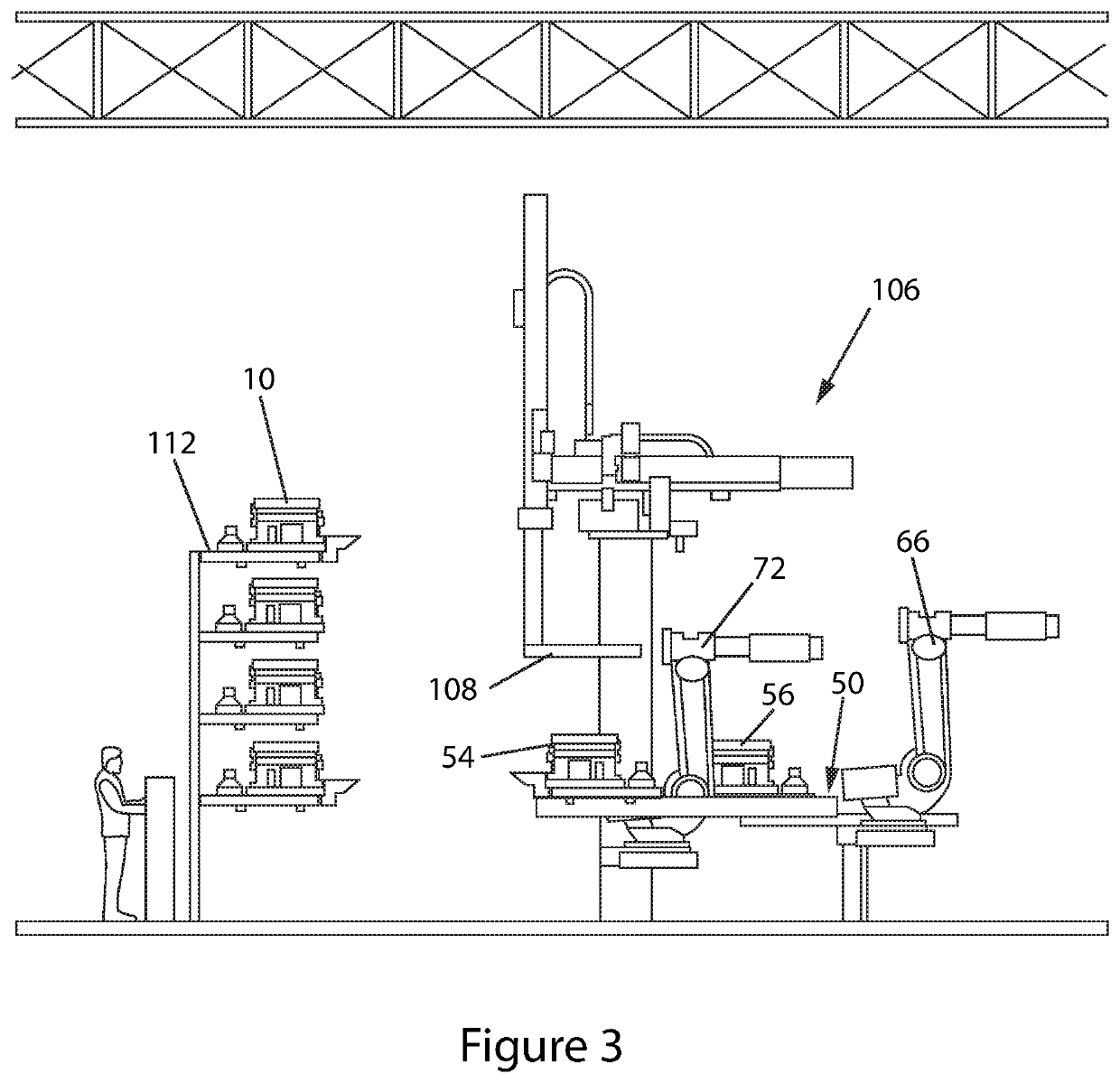
[0025]The advantages of the invention will be described with reference to an exemplary embodiment of the invention for formation of an engine block mold, illustrated in the attached FIGS. 1 to 4, where the same numerals are used in the different figures to designate the same or similar elements for easier reading and understanding of the principles of the invention.

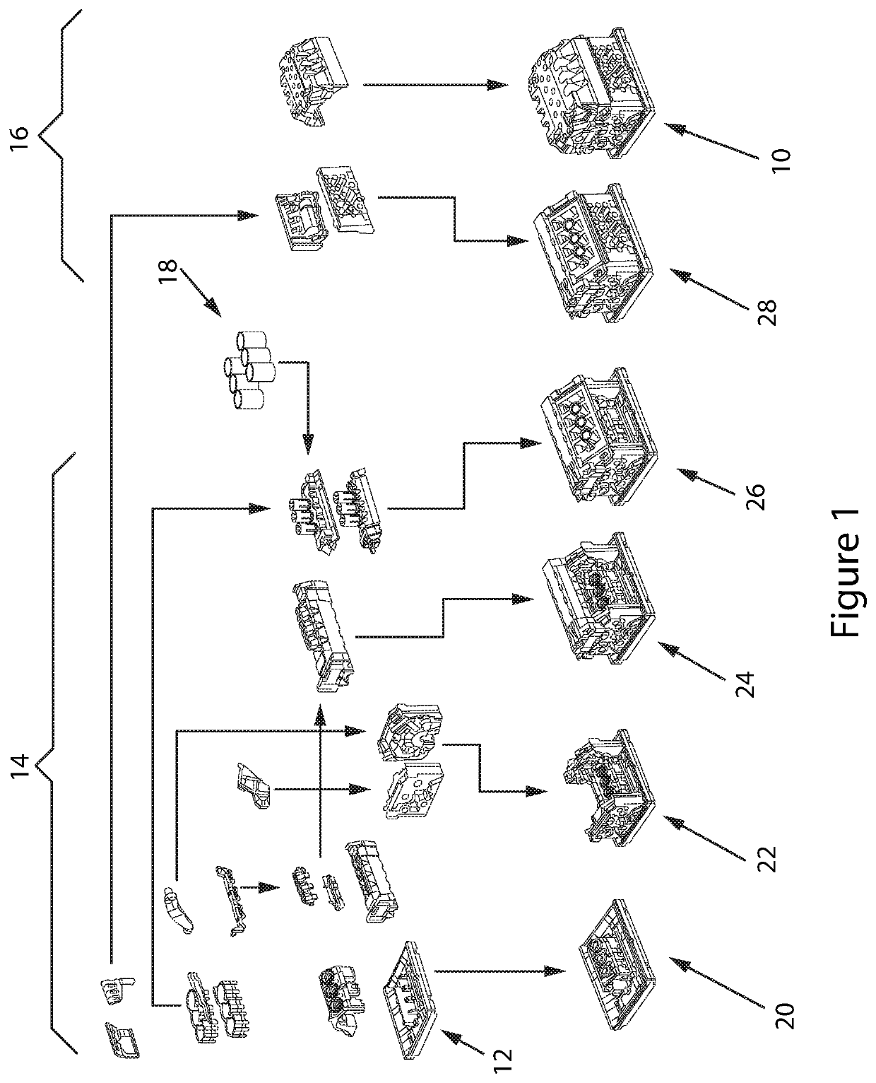
[0026]Referring to FIG. 1, a finished mold package 10 ready for casting an engine block is formed by sequentially assembling the cores and components of the casting progressively starting from a core base 12 where the variety of sand cores 14 and 16 and metal cylinde...


PUM

PropertyMeasurementUnit
shapeaaaaaaaaaa
flexibilityaaaaaaaaaa
distanceaaaaaaaaaa

Abstract

A mold assembly cell for sand mold production comprising a turntable wherein sand cores and other mold parts (which together cooperate to define the casting cavity of the sand mold) are automatically and progressively assembled following a sequential pre-programmed schedule by programmable robots located in proximal relationship with the turntable and a core shooting machine. The assembly turntable rotates clockwise or counterclockwise to permit placement of progressively more-complete mold packages in each of at least three assembly stations to allow the robots to reach the molds being assembled at different angles for simultaneously setting the sand cores and other parts of the mold according to said pre-programmed assembly schedule. Also a mold assembly line comprising a plurality of the foregoing assembly cells to form sand molds for casting complex-geometry aluminum parts, such as aluminum engine blocks and cylinder heads, with greater flexibility, efficiency and productivity.

Description

FIELD OF THE INVENTION[0001]The present invention relates to the field of foundries and casting operations, more particularly to methods and systems for assembling sand cores to form sand molds for casting complex-geometry aluminum parts, such as engine blocks and cylinder heads, with higher flexibility, efficiency and productivity than the currently used methods, tools and mold assembly lines.BACKGROUND OF THE INVENTION[0002]For high-volume casting of engine blocks and other automotive and aviation components of light metals such as aluminum, the widely used casting process in the automotive industry is the precision sand casting. The castings are formed into sand molds, usually resin-bonded. The sand mold defines the complex casting geometry by means of a set of sand cores which are sequentially assembled with high precision in a predefined sequence and form mold core packages. After casting, the mold is heated and the resin, that fixes the sand of the cores, is burned with a cons...

Claims


Application Information

Patent Timeline
Patent Type & Authority Patents(United States)
IPC IPC(8): B22C25/00B22C9/10B22C9/02B22C23/00B22D47/02
CPCB22C9/02B22C9/103B22C9/108B22C25/00B22C23/00B22D47/02
Inventor SALAS-LORANCA, GERMAN GABRIELCANTU-GONZALEZ, OSCAR GERARDO
Owner NEMAK S A B DE
Why Eureka
Try Eureka