Inverter control device

a technology of inverter control and control device, which is applied in the direction of electric generator control, dynamo-electric converter control, dynamo-electric gear control, etc., can solve the problems of increasing the total frequency of driving hybrid vehicles using internal combustion engines, difficulty in obtaining correct temperature information of inverter, and incorrect results of abnormality detection. achieve the effect of avoiding disadvantages, and increasing the temperature value of inverter

Active Publication Date: 2021-07-20
DENSO CORP
View PDF14 Cites 0 Cited by
  • Summary
  • Abstract
  • Description
  • Claims
  • Application Information

AI Technical Summary

Benefits of technology

[0008]It is therefore desired to provide an inverter control device capable of placing an inverter into an executable temperature range so as to correctly execute abnormality detection of a detection target in a motor generator control system mounted on a hybrid vehicle even if the inverter has a current temperature outside the executable temperature range.
[0014]Under cold conditions, which corresponds to the low temperature state of a hybrid vehicle, because the inverter has a low temperature, it is difficult to correctly perform the abnormality detection when the hybrid vehicle starts to use the engine. When the hybrid vehicle starts to use the engine under cold conditions, it is effective to supply energy to the inverter so as to increase the temperature value of the inverter and to allow the temperature value of the inverter into the diagnosable temperature range. For example, the energy to be supplied to the inverter is electric power or heat energy so as to increase the inverter temperature value within the diagnosable temperature range. When the inverter temperature value reaches the diagnosable temperature range, the abnormality detection part correctly perform the abnormality detection. This abnormality detection control previously described makes it possible to increase an execution frequency of performing the abnormality detection for the motor generator control system within a predetermined period of time counted from the engine start of the hybrid vehicle. This control makes it possible to quickly avoid a disadvantageous condition of the hybrid vehicle which does not match the laws and regulations even if the hybrid vehicle is in severe cold environment such as under cold conditions.
[0015]When the inverter control device uses one or more temperature sensors having a wide temperature range, which expands the diagnosis executable temperature range, so as to satisfy the maximum temperature range when the hybrid vehicle starts to use the engine, this increases the manufacturing cost of the inverter control device and the MG control system.
[0016]The inverter control device according to the present invention has the improved structure capable of adjusting the energy to be supplied to the inverter without using any expensive temperature sensor, and capable of increasing the number of times to perform the abnormality detection within the predetermined period of time counted from the engine start of the hybrid vehicle.
[0017]Still further, in the improved structure of the inverter control device, the diagnosis executable temperature range is determined and adjusted on the basis of the detectable temperature range of the inverter temperature sensor. This avoids the incorrect execution of the abnormality detection in the condition which is outside the temperature detectable range of each temperature sensor.

Problems solved by technology

In the structure of the motor generator control system previously described, it is difficult for the controller device to acquire correct temperature information of the inverter if the detected temperature value of the inverter is outside a detectable temperature range of a temperature sensor.
This often causes an incorrect result of the abnormality detection.
However, the related art such as patent document 1 discloses and suggests no relationship between the detectable temperature range of the temperature sensor and the diagnosable temperature range of the inverter.
In such a hybrid vehicle, when inverter failure or motor generator failure reduces the frequency of driving the hybrid vehicle by using electric power, the total frequency of driving the hybrid vehicle using the internal combustion engine increases and this state increases the amount of exhaust gas emission.
The increased amount of exhaust gas emission causes environmental damage.
Accordingly, when a detected inverter temperature value of the inverter is outside the specific detectable temperature range, the motor generator control system cannot correctly perform the abnormality detection.
Accordingly, there is a possible defect case in which the motor generator control system mounted on a hybrid vehicle does not match and does not satisfy the laws and regulations previously described in each country or region.
On the other hand, when the motor generator control system uses a temperature sensor having a wide detectable temperature range so as to conform to the laws and regulations, this increases manufacturing cost.
The motor generator control system failure includes abnormality of demagnetization characteristics of the motor generator, abnormality of torque characteristics of the motor generator, occurrence of a short circuit or disconnection in phase windings of the motor generator, abnormality of sensors such as temperature sensor failure, etc.
Under cold conditions, which corresponds to the low temperature state of a hybrid vehicle, because the inverter has a low temperature, it is difficult to correctly perform the abnormality detection when the hybrid vehicle starts to use the engine.
When the inverter control device uses one or more temperature sensors having a wide temperature range, which expands the diagnosis executable temperature range, so as to satisfy the maximum temperature range when the hybrid vehicle starts to use the engine, this increases the manufacturing cost of the inverter control device and the MG control system.

Method used


Image

  • Inverter control device
  • Inverter control device
  • Inverter control device

Examples


first exemplary embodiment

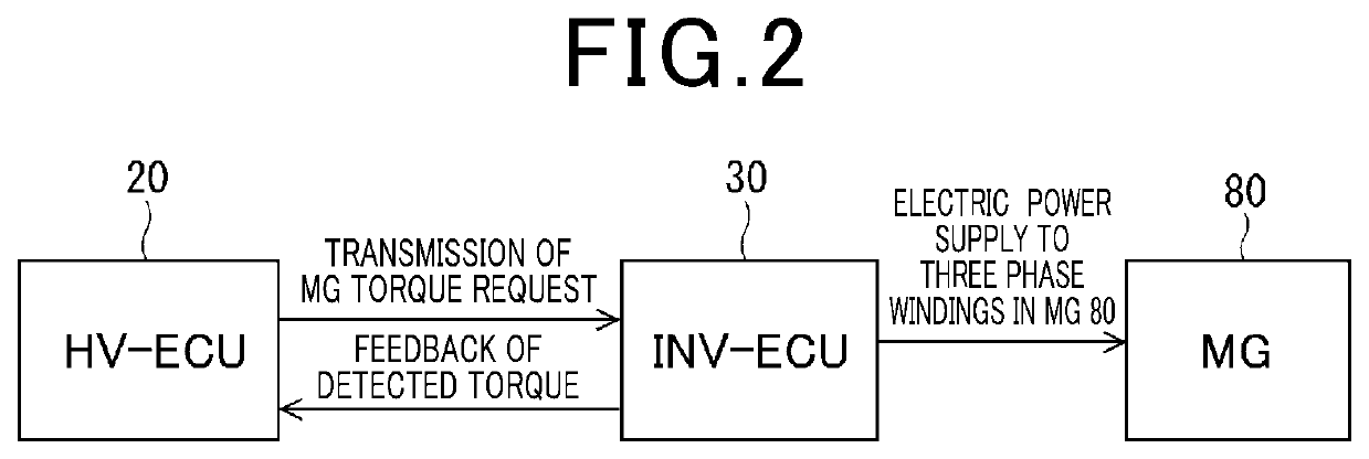
[0037]A description will be given of the INV ECU 30 as the inverter control device according to the first and second exemplary embodiments with reference to FIG. 1 to FIG. 7.

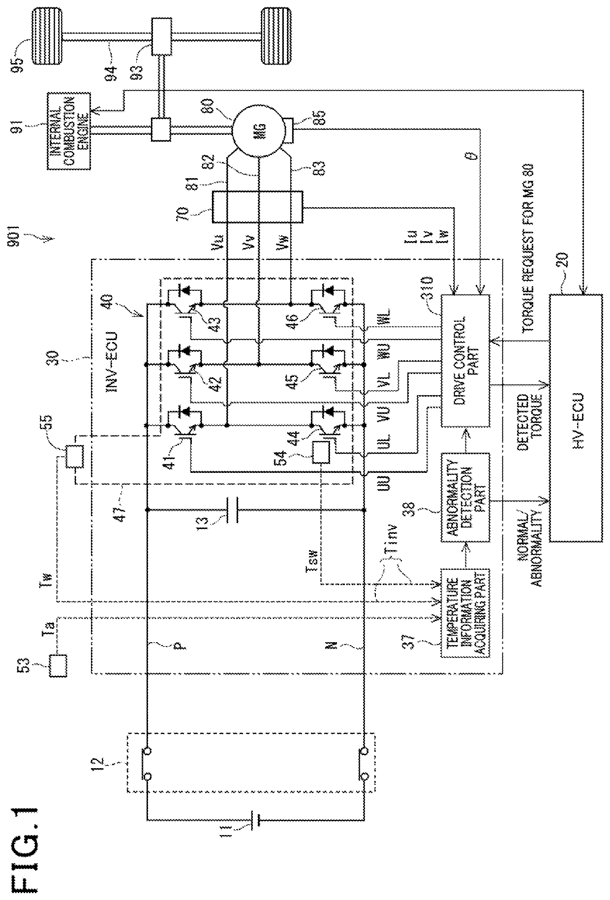
[0038]FIG. 1 is a view showing a schematic structure of the MG control system mounted on the hybrid vehicle 901, to which the INV ECU 30 as the inverter control device according to the first exemplary embodiment and the second exemplary embodiment is applied.

[0039]A description will now be given of a schematic structure of the MG control system of the hybrid vehicle 901 with reference to FIG. 1.

[0040]A battery 11 is composed of a rechargeable battery capable of performing charging and discharging such as a nickel-metal hydride battery, a lithium ion battery, etc. A positive electrode of the battery 11 is connected to a high voltage line P, and a negative electrode of the battery 11 is connected to a low voltage line N. The high voltage line P and the low voltage line N are power supply lines.

[0041]It is acceptab...

second exemplary embodiment

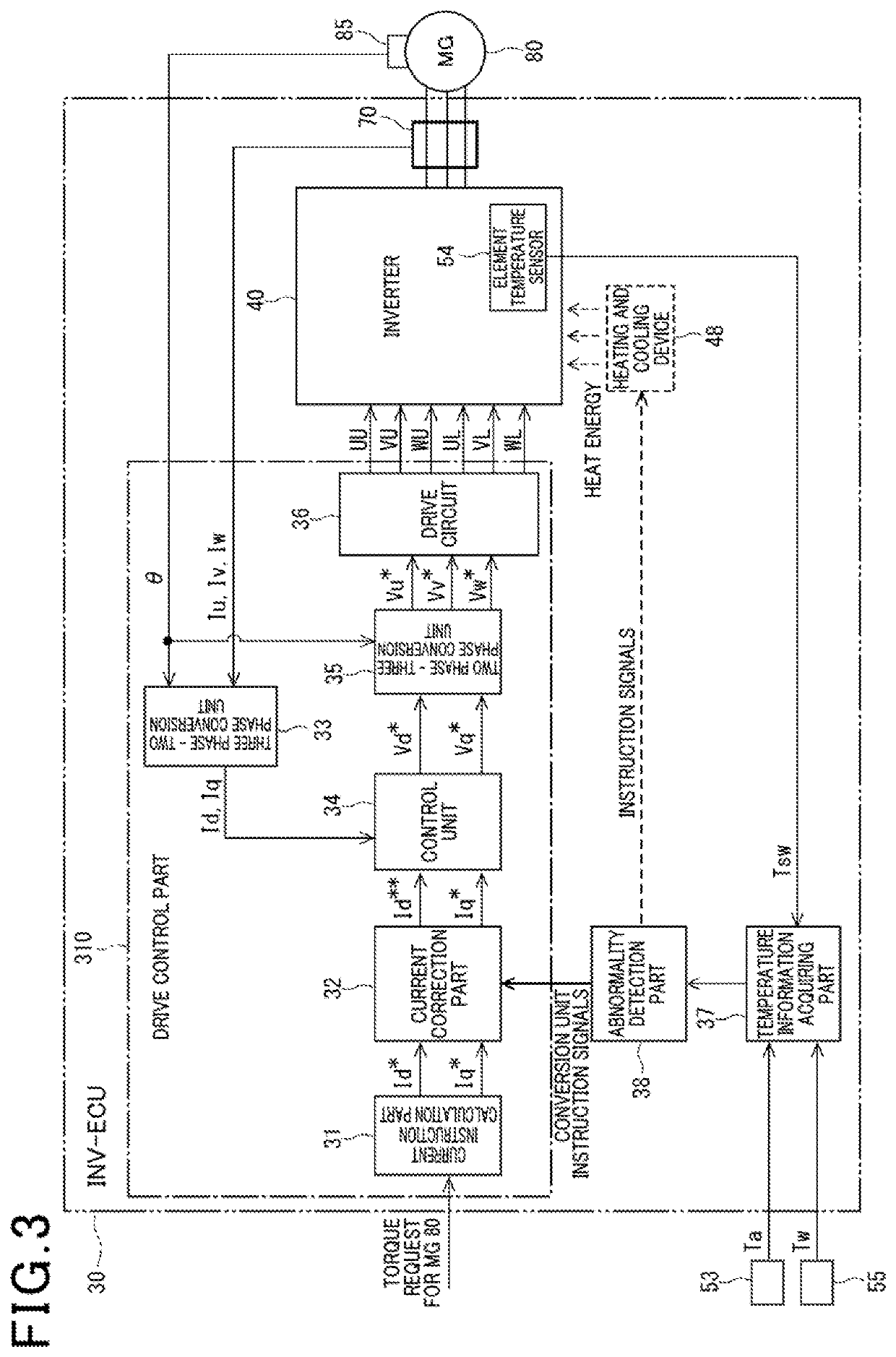
[0146]A description will be given of the INV ECU 30 according to the second exemplary embodiment. The INV ECU 30 according to the second exemplary embodiment has the same structure of the INV ECU according to the first exemplary embodiment shown in FIG. 1 to FIG. 3.

[0147]In particular, the INV ECU 30 according to the second exemplary embodiment adjusts the heat energy to be supplied to the inverter 40 when the inverter temperature value Tinv of the inverter 40 is outside the diagnosis executable temperature range. In other words, the INV ECU 30 according to the second exemplary embodiment adjusts the heat energy to be supplied to the inverter 40. On the other hand, as previously described, the INV ECU 30 according to the first exemplary embodiment adjusts the amount of electric power to be supplied to the inverter 40 when the inverter temperature value Tinv of the inverter 40 is outside the diagnosis executable temperature range.

[0148]As shown by the dotted line shown in FIG. 3, the...

third exemplary embodiment

[0158]A description will be given of the INV ECU 30 according to a third exemplary embodiment with reference to FIG. 8 to FIG. 10.

[0159]FIG. 8 is a view showing a schematic structure of the MG control system mounted on a plug-in type hybrid vehicle 903, to which an INV ECU 30 according to the third exemplary embodiment of the present invention is applied. As shown in FIG. 8, the INV ECU 30 according to the third exemplary embodiment is applied to the MG control system or a MG drive system for the plug-in type hybrid vehicle 903.

[0160]The plug-in type hybrid vehicle 903 is equipped with a power supply connector 17. An external plug-in cable 16 is connected to the power supply connector 17 in the plug-in type hybrid vehicle 903 so as to supply electric power to the plug-in type hybrid vehicle 903.

[0161]In more detail, first terminals of an external power supply relay 18 are connected to the power supply connector 17, and second terminals of the external power supply relay 18 are conne...


PUM


Abstract

An inverter ECU is applied to a hybrid vehicle having an engine and a motor generator as drive power source and a motor generator control system. A drive control part generates drive signals for an inverter based on torque request to the motor generator. A temperature information acquiring part acquires an element temperature value and a cooling water temperature value as an inverter temperature value. An abnormality detection part detects whether the inverter temperature value is within a diagnosable temperature range, and performs abnormality detection for the motor generator control system when the inverter temperature value is within the diagnosable temperature range. When the inverter temperature value is not placed within the diagnosable temperature range, the energy supplied to the inverter is adjusted to move the inverter temperature value into the diagnosis allowable temperature range to correctly perform the abnormality detection.

Description

CROSS-REFERENCE TO RELATED APPLICATION[0001]This application is related to and claims priority from Japanese Patent Application No. 2017-106886 filed on May 30, 2017, the contents of which are hereby incorporated by reference.BACKGROUND OF THE INVENTION1. Field of the Invention[0002]The present invention relates to inverter control devices for performing supply control of electric power to a motor generator as a drive power source mounted on various types of hybrid vehicles.2. Description of the Related Art[0003]There has been known a technique to perform abnormality detection of a motor generator control system mounted on a hybrid vehicle. For example, patent document 1, Japanese registered patent No. 4333759 has disclosed a motor generator control system mounted on a hybrid vehicle which is equipped with an electric generator and an electric motor. The controller device is configured to perform abnormality detection so as to detect occurrence of electric generator failure. An inve...

Claims


Application Information

Patent Timeline
Patent Type & Authority Patents(United States)
IPC IPC(8): B60L3/00H02P29/68H02P21/06B60L50/16
CPCB60L3/003B60L3/0061H02P21/06H02P29/68B60L2240/36B60L2250/26B60Y2200/92Y10S903/906B60W20/15B60W10/08B60W20/50B60W2710/08B60W2530/00
Inventor NISHIYAMA, MASAKIYAMASHITA, HIROFUMI
Owner DENSO CORP
Why Eureka
Try Eureka