Transmittance-variable device

a transmission variable and transmission angle technology, applied in the field can solve the problems of shifted viewing angle characteristics in the vertical direction, poor transmission angle characteristics of transmission variable devices, etc., and achieve the effects of high transmittance, high shielding rate, and high contrast ratio

Active Publication Date: 2021-08-24
LG CHEM LTD
View PDF22 Cites 0 Cited by
  • Summary
  • Abstract
  • Description
  • Claims
  • Application Information

AI Technical Summary

Benefits of technology

[0113]The transmittance-variable device of the present application can switch between a transparent state and a black state, can exhibit high transmittance in the transparent state and a high shielding rate in the black state, and can exhibit a high contrast ratio even at the inclination angle and exhibit symmetric viewing angle characteristics in all directions. Such a transmittance-variable device of the present application can be applied to various applications including various architectural or automotive materials which need to adjust the transmittance, or eyewear such as goggles for augmented reality experience or sports, sunglasses or helmets.EXPLANATION OF REFERENCE NUMERALS
[0121]Hereinafter, the transmittance-variable device of the present application will be described in detail by way of examples and comparative examples, but the scope of the present application is not limited by the following transmittance-variable device.

Problems solved by technology

A problem that such a transmittance-variable device has is poor viewing angle characteristics.
For example, if a black state is implemented by overlapping two GH cells and then crossing the optical axes of the respective GH cells, there is a problem that even when the viewing angle characteristics in the horizontal direction are symmetrical, the viewing angle characteristics in the vertical direction are shifted to one side.

Method used


Image

  • Transmittance-variable device
  • Transmittance-variable device
  • Transmittance-variable device

Examples


example 1

[0122]A first GH cell was produced by forming a GH layer between two COP (cycloolefin polymer) films in which an ITO (indium tin oxide) electrode layer and a vertical alignment film were sequentially formed on the surface. Here, the cell gap of the GH cell was set to about 12 μm. Here, as the vertical alignment film, an alignment film having a pretilt angle of about 89 degrees was used. The alignment film was formed to a thickness of about 200 nm by coating a polyimide-based vertical alignment film on the ITO electrode layer by bar coating, holding the film at 130° C. for about 30 minutes and then rubbing the film with a rubbing cloth. At this time, the two COP films were laminated so that the rubbing directions of the alignment films on the films were opposite to each other. Also, the GH layer was formed by applying a GH mixture in which nematic liquid crystals having dielectric constant anisotropy of about −4.9 and refractive index anisotropy of about 0.132 as a liquid crystal com...

example 2

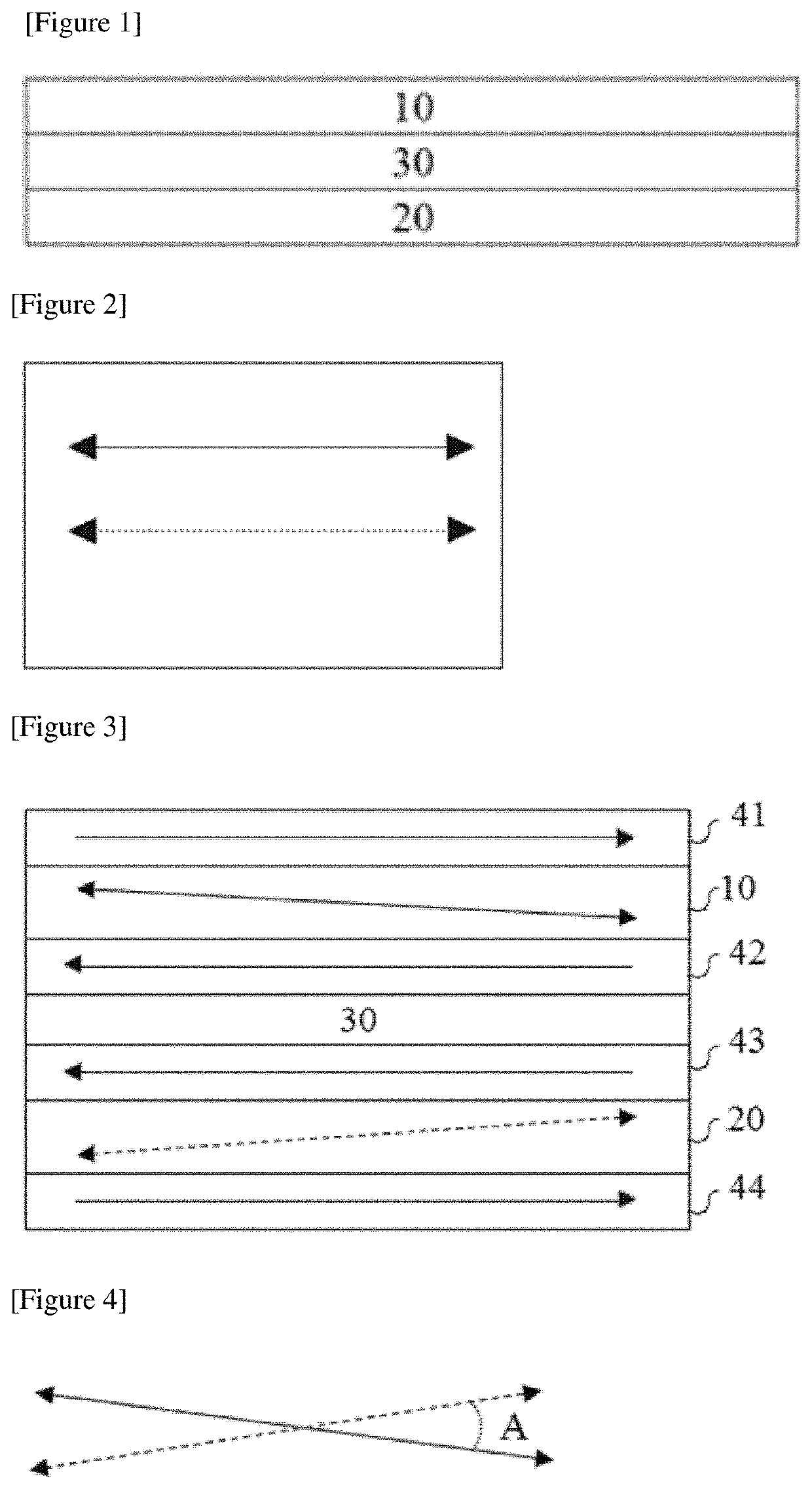
[0123]A transmittance-variable element was manufactured in the same manner as in Example 1, except that as the phase difference element (30 in FIG. 3) introduced between the first and second GH cells, a laminated film of a COP (cycloolefin polymer) film having a plane phase difference of about 275 nm for a wavelength of 550 nm and having a flat wavelength characteristic and Nz (=(nx−nz) / (nx−ny), wherein nx is a refractive index in the slow axis direction, ny is a refractive index in the fast axis direction, and nz is a refractive index in the thickness direction) of about 1.2 and a vertical alignment liquid crystal layer having a thickness direction phase difference (Rth=dx(nz−ny)) in a range of about 180 to 200 nm was placed.

example 3

[0124]A transmittance-variable element was manufactured in the same manner as in Example 1, except that as the phase difference element (30 in FIG. 3) introduced between the first and second GH cells, a laminated film of a COP (cycloolefin polymer) film from having a plane phase difference of about 275 nm for a wavelength of 550 nm and having a reverse wavelength characteristic and a ratio (Re (450) / Re (550)) of a plane phase difference (Re (450)) for light with a wavelength of 450 nm to a plane phase difference (Re (550)) for light with a wavelength of 550 nm of about 0.8 or so and a vertical alignment liquid crystal layer having a thickness direction phase difference (Rth=dx(nz−ny)) of about 100 nm or so was placed.


PUM

PropertyMeasurementUnit
pretilt angleaaaaaaaaaa
thicknessaaaaaaaaaa
wavelengthaaaaaaaaaa

Abstract

A transmittance-variable device is disclosed herein. In some embodiments, a transmittance-variable device includes first and second guest host layers, the first and second guest host layers are superposed, wherein each of the first and second guest host layers comprise a liquid crystal host and a dichroic dye guest, and wherein the device is capable of switching between a transparent mode and a black mode. The transmittance-variable device can exhibit high transmittance in the transparent state and a high shielding rate in the black state, and can exhibit a high contrast ratio even at the inclination angle, and exhibit excellent viewing angle symmetry in all directions. Such a transmittance-variable device can be applied to various applications including various architectural or automotive materials which need to adjust the transmittance, or eyewear such as goggles for augmented reality experience or sports, sunglasses or helmets.

Description

CROSS-REFERENCE TO RELATED APPLICATION(S)[0001]The present application is a national phase entry under 35 U.S.C. § 371 of International Application No. PCT / KR2018 / 012987, filed on Oct. 30, 2018, which claims priority from Korean Patent Application No. 10-2017-0143741, filed on Oct. 31, 2017, the disclosures of which are incorporated by reference herein.TECHNICAL FIELD[0002]The present application relates to a transmittance-variable device.BACKGROUND ART[0003]A transmittance-variable device using a so-called GH cell (guest host cell), to which a mixture of a host material, which is mainly a liquid crystal compound, and a dichroic dye guest is applied, is known (for example, Patent Document 1).[0004]Such a transmittance-variable device is applied to various applications including eyewear such as sunglasses, building outer walls, vehicle sunroofs and the like. Recently, application of the transmittance-variable element to eyewear for the so-called augmented reality (AR) experience has ...

Claims


Application Information

Patent Timeline
Patent Type & Authority Patents(United States)
IPC IPC(8): G02F1/1337G02F1/1347G02F1/1335G02B27/01G02C7/10
CPCG02F1/1337G02B27/01G02C7/101G02F1/1347G02F1/13475G02B27/0172G02C7/12
Inventor LIM, EUN JUNGBELYAEV, SERGEYOH, DONG HYUNYOU, JUNG SUNKIM, JIN HONGLEE, HYUN JUNGIM, MIN JUN
Owner LG CHEM LTD
Why Eureka
Try Eureka