Supercapacitor with electrolyte

a supercapacitor and electrolyte technology, applied in the direction of hybrid/edl capacitor protection/adjusting, instruments, hybrid/edl manufacture, etc., can solve the problem of remaining limited by the total amount of charges, and achieve the effect of multiplying the charges stored and ensuring safety

Active Publication Date: 2021-11-09
CENT NAT DE LA RECHERCHE SCI +3
View PDF13 Cites 0 Cited by
  • Summary
  • Abstract
  • Description
  • Claims
  • Application Information

AI Technical Summary

Benefits of technology

[0055]According to tests performed on a material of the A2B2O5 type defined above, the first temperature is for example on the order of or greater than 60° C. and the second temperature is around room temperature, typically 20° C. Note that thermal locking also has an advantage in terms of safety in comparison to conventional batteries which have a known risk of explosion due to thermal runaway, since any abnormal rise in temperature of the material automatically cuts off the delivery of current and puts an immediate end to thermal runaway.
[0056]In an application of the device where it is configured as a battery (for storing or discharging an electric charge respectively into or from the electrolyte), it is advantageous for the solid ion-conductive material to comprise microcrystals (in particular for trapping charges in grain boundaries and thus multiplying the charges stored).

Problems solved by technology

In that document, the electrolyte material is a liquid, which may cause problems in the fabrication and packaging of supercapacitors comprising such a liquid electrolyte solution, in particular for memory fabrication applications.
In addition, although the capacitance obtained is much higher than that of conventional capacitors due to the small thickness of the double layers, it remains limited by the total amount of charges that can accumulate in the double layers.

Method used


Image

  • Supercapacitor with electrolyte
  • Supercapacitor with electrolyte
  • Supercapacitor with electrolyte

Examples


first embodiment

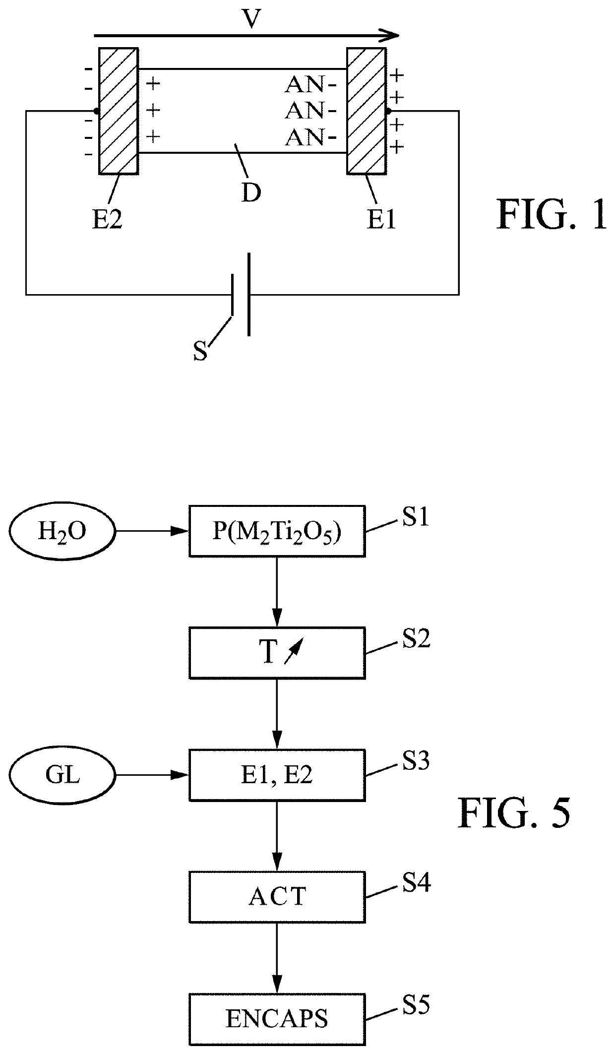
[0096]In a first embodiment, the temperature is raised locally in the material by several tens of degrees (for example up to 60° C.). The spontaneous current is then seen to cease, as shown in FIG. 6. The current is restored spontaneously when the temperature returns to room temperature, without requiring any other charge process. The local increase in temperature may be produced by various means, for example by laser, radiofrequency, or resistive heating, or by Peltier module.

second embodiment

[0097]In a second embodiment, alternatively or in combination, it is possible to vary appropriately the pressure load on the material in order to “lock” any discharge and maintain the charge in the electrolyte, by applying a mechanical force. Then, the application of a different force (for example a “null” force with release of the pressure) allows releasing the charge from the electrolyte and thus retrieving the current that was stored therein. The mechanical force may be applied by mechanical, piezoelectric, electrostrictive, magnetostrictive, or magneto-mechanical systems for example.

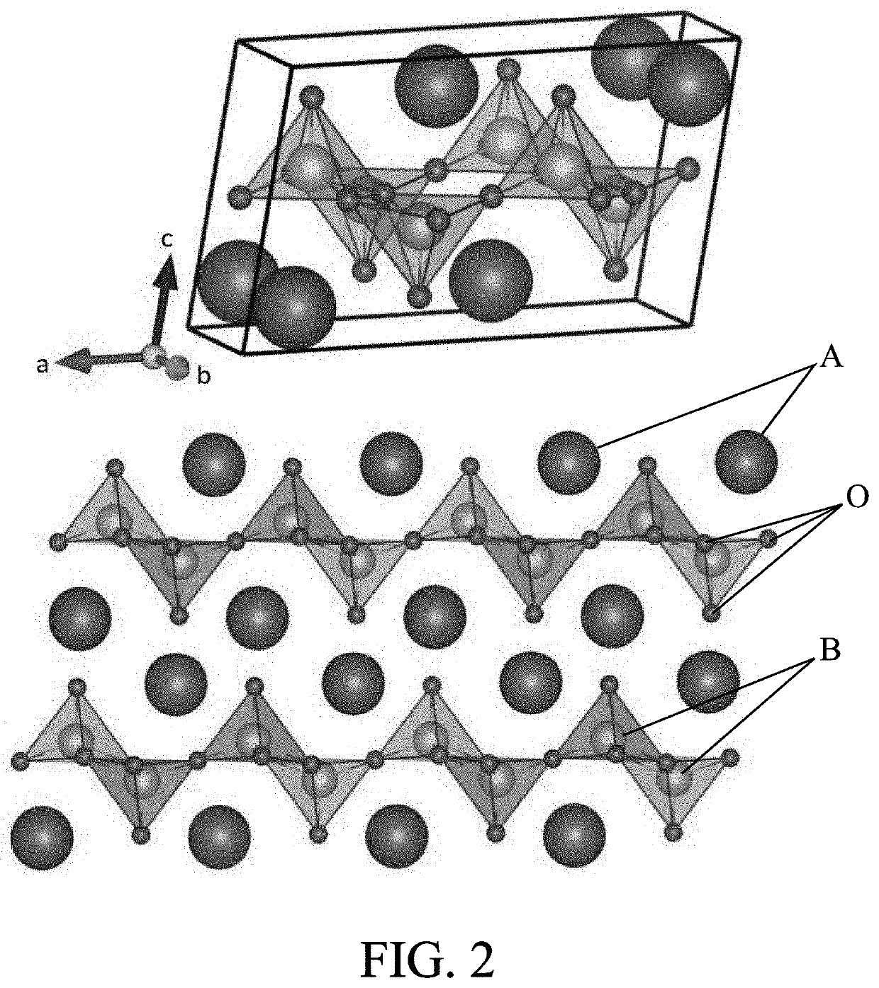
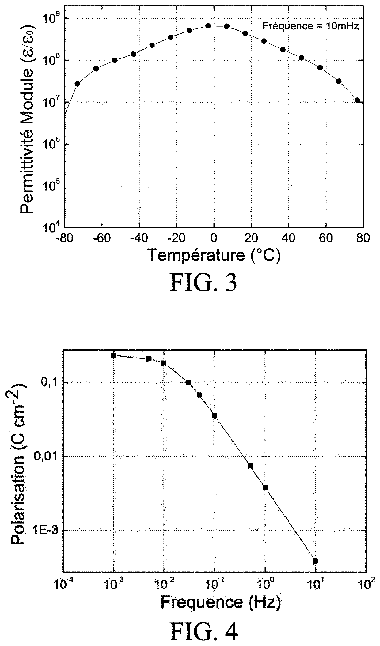
[0098]Supercapacitors based on a solid ion-conductive material, particularly of the M2Ti3O5 type, have charge storage densities that exceed the performance of existing supercapacitor devices because of the very high dielectric constant and therefore the very strong polarization induced in the material (typically 0.1 C / cm2), for a low electron conduction.

[0099]Unless the charges of the electrolyte mat...


PUM

PropertyMeasurementUnit
temperatureaaaaaaaaaa
dielectric constantsaaaaaaaaaa
sizeaaaaaaaaaa

Abstract

The invention relates to a supercapacitor comprising:
    • an electrolyte having a first end and a second end opposite the first end,
    • a first electrode in contact with the first end of the electrolyte, and
    • a second electrode in contact with the second end of the electrolyte.
In particular, the electrolyte is made of a solid material that is ion-conductive and electronically insulating.

Description

CROSS-REFERENCE TO RELATED APPLICATION[0001]This Application is a 35 USC § 371 US National Stage filing of International Application No. PCT / FR2017 / 052678 filed on Sep. 29, 2017, and claims priority under the Paris Convention to French Patent Application No. 1659322 filed on Sep. 29, 2016.FIELD OF THE DISCLOSURE[0002]The invention relates to the field of capacitor-type electrical or electronic components, in particular for energy or information storage.[0003]It more particularly relates to a supercapacitor.BACKGROUND OF THE DISCLOSURE[0004]Midway between capacitors fabricated by electrodeposition (“electrolytic”) and rechargeable batteries, supercapacitors have the advantage of being faster to charge and discharge than batteries and of providing more storage than electrolytic capacitors.[0005]However, their stored energy density remains three to four times lower than that of batteries. They are therefore used as a complement to batteries.[0006]In comparison to conventional capacitor...

Claims


Application Information

Patent Timeline
Patent Type & Authority Patents(United States)
IPC IPC(8): H01G11/56H01L45/00H01G11/14H01G11/84C04B35/462H01G11/30G11C13/00G11C13/02
CPCH01G11/56C04B35/462H01G11/14H01G11/30H01G11/84H01L45/08H01L45/147C04B2235/3201G11C13/0009G11C13/02Y02E60/13H10N70/24H10N70/8836
Inventor LERIDON, BRIGITTEHOLE, STÉPHANEFEDERICCI, RÉMI
Owner CENT NAT DE LA RECHERCHE SCI
Why Eureka
Try Eureka