Method and device for generating a nuclear magnetic resonance spectrum of nuclear spin moments of a sample

Active Publication Date: 2021-11-23
PLENIO MARTIN BODO +3
View PDF17 Cites 1 Cited by
  • Summary
  • Abstract
  • Description
  • Claims
  • Application Information

AI Technical Summary

Benefits of technology

[0058]In one advantageous development, the or each detection spin moment is arranged in the region of a nanostructuring introduced into the solid. The nanostructuring preferably has a simple geometry. In particular, so-called nanoslits, that is to say elongate, slit-like cutouts, in the surface of the solid are possible in this case. By virtue of the simple geometry, the nanostructuring is able to be produced in a simple manner and with little outlay. Preferably, an arrangement or an array of nanoslits is provided in this case. As a result, the surface area of the solid—and thus the contact area with the sample—is significantly increased. This is transferred as a consequence to the polarization step in particula

Problems solved by technology

As a result, the spatial resolution of such inductive methods is restricted to comparatively large samples, as a result of which the spatial resolution in a nuclear magnetic resonance examination is disadvantageously limited.
In this case, the spectral resolution is substantially limited by the comparatively low relaxation time of the detection spin moments.
In this case, the spectral resolution of the nuclear magnetic resonance spectrum is limited by the stability of the oscillator, such that high-resolution nuclear magnetic resonance spectra of the sample are made possible.
In the case of nuclear spin moments in liquid samples, however, the spectral resolution is limited on account of the finite dimensions of the detectio

Method used


Image

  • Method and device for generating a nuclear magnetic resonance spectrum of nuclear spin moments of a sample
  • Method and device for generating a nuclear magnetic resonance spectrum of nuclear spin moments of a sample
  • Method and device for generating a nuclear magnetic resonance spectrum of nuclear spin moments of a sample

Examples


Example

[0071]Mutually corresponding parts and variables are always provided with the same reference signs in all the figures.

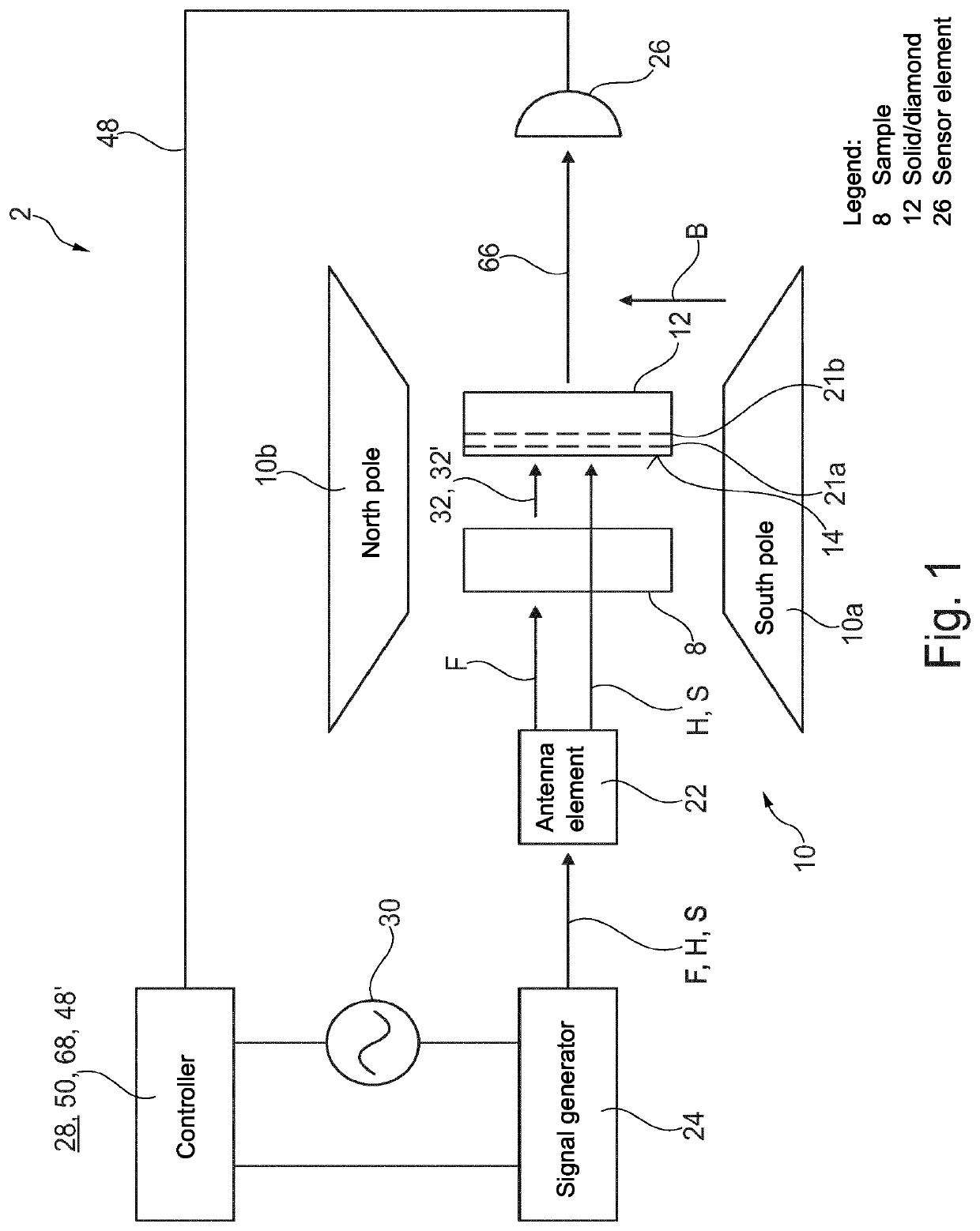
[0072]The device 2 illustrated in FIG. 1 is suitable and configured for generating a nuclear magnetic resonance spectrum 4 (FIG. 8) of nuclear spin moments 6 (FIG. 2a, FIG. 2b) of a sample 8. The device 2 comprises a magnet 10, having a north pole 10a and a south pole 10b, between which a homogeneous magnetic field B is generated during operation. During operation, the sample 8 together with a solid 12 is positioned for example in a region of the magnet 10 that is freed between the north pole 10a and south pole 10b.

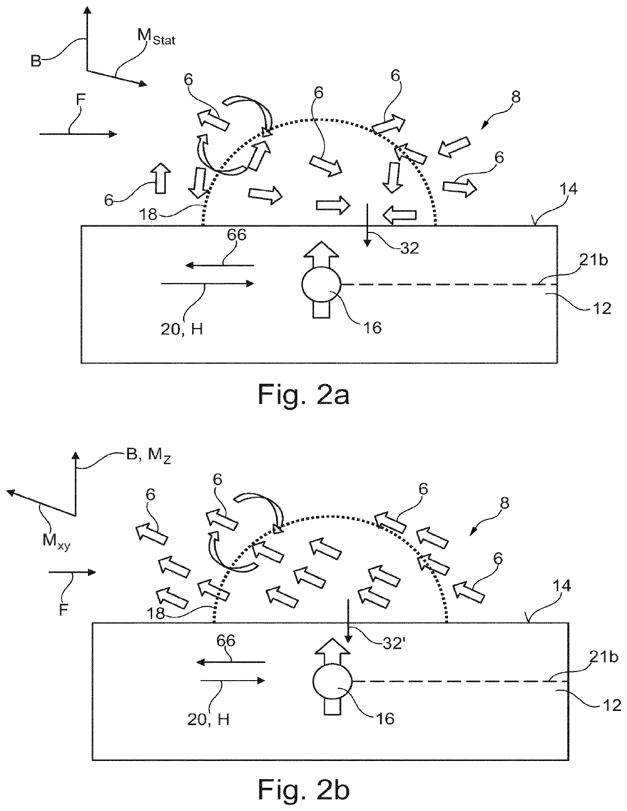
[0073]The sample 8 is a liquid material sample, for example, which is applied on the surface 14 of the solid 12. As illustrated schematically and in a simplified manner in FIG. 2a and FIG. 2b, the sample 8 has a number of nuclear spin moments 6. The nuclear spin moments 6 are provided with reference signs merely by way of example in FIGS. 2a and 2b. The s...


PUM


Abstract

A method for generating a nuclear magnetic resonance spectrum of nuclear spin moments of a sample includes a static magnetic field permeating the sample, and a detection spin moment with a detection region surrounding the latter. The detection region extends at least partly into the sample. The method also includes an antenna element for radiating in frequency pulses for influencing the nuclear spin moments and radio-frequency pulses for influencing the detection spin moment, where a polarization step involves polarizing at least one portion of the nuclear spin moments along the magnetic field to form a longitudinal magnetization, where a transfer step involves converting the longitudinal magnetization (Mx) into a transverse magnetization (Mxy) by radiating in a frequency pulse (F) with a 90° flip angle, wherein a detection step involves radiating in a sequence of radio-frequency pulses onto the detection spin moment and subsequently detecting a signal (32′) of the transverse magnetization (Mxy) present in the detection region and storing the signal as detection result in a list. The detection step is carried out a number of times repeatedly in succession, wherein the polarization step and the transfer step and also the detection steps are carried out.

Description

CROSS-REFERENCE TO RELATED APPLICATIONS[0001]This application is a national phase application of International Application No. PCT / EP2018 / 064481, filed Jun. 1, 2018, which claims the benefit of German Application No. DE 102017210309.4, filed Jun. 20, 2017 and German Application No. DE 102017209453.2, filed Jun. 2, 2017, all of which are incorporated herein by reference.BACKGROUND OF THE INVENTIONField of the Invention[0002]The invention relates to a method for generating a nuclear magnetic resonance spectrum of nuclear spin moments of a sample, comprising a static magnetic field permeating the sample, and a detection spin moment with a detection region surrounding the latter, said detection region extending at least partly into the sample, and also an antenna element for radiating in frequency pulses for influencing the nuclear spin moments and radio-frequency pulses for influencing the detection spin moment. The invention furthermore relates to a device for carrying out the method....

Claims


Application Information

Patent Timeline
IPC IPC(8): G01N24/10G01N24/08G01R33/28G01R33/44G01R33/46
CPCG01N24/10G01N24/08G01R33/282G01R33/448G01R33/4608G01N24/12G01R33/323G01R33/62
Inventor PLENIO, MARTIN BODOSCHWARTZ, ILAIMCGUINNESS, LIAMROSSKOPF, JOACHIM
Owner PLENIO MARTIN BODO
Why Eureka
Try Eureka