

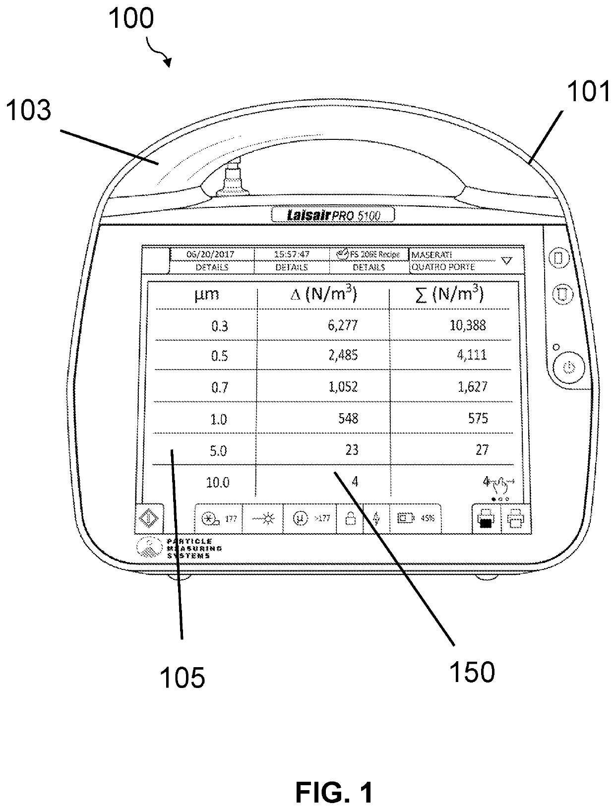
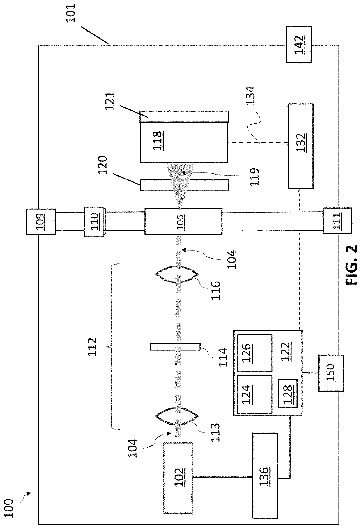
Antimicrobial particle detectors
a particle detector and antimicrobial technology, applied in the field of particle detectors, can solve the problems of pharmaceutical products at risk of failing to meet the cleanliness level standards, real-time efficiency, and fabrication efficiency drop
- Summary
- Abstract
- Description
- Claims
- Application Information
AI Technical Summary
Benefits of technology
Problems solved by technology
Method used
Image

Examples
Embodiment Construction
[0052]In general, the terms and phrases used herein have their art-recognized meaning, which can be found by reference to standard texts, journal references and contexts known to those skilled in the art. The following definitions are provided to clarify their specific use in the context of the invention.
[0053]“Particle” refers to a small object which is often regarded as a contaminant. A particle can be any material created by the act of friction, for example when two surfaces come into mechanical contact and there is mechanical movement. Particles can be composed of aggregates of material, such as dust, dirt, smoke, ash, water, soot, metal, minerals, or any combination of these or other materials or contaminants. “Particles” may also refer to biological particles, for example, viruses, spores and microorganisms including bacteria, fungi, archaea, protists, other single cell microorganisms. Biological particles include, but are not limited to, microorganisms having a size on the or...
PUM
| Property | Measurement | Unit |
|---|---|---|
| thickness | aaaaa | aaaaa |
| thickness | aaaaa | aaaaa |
| thickness | aaaaa | aaaaa |
Abstract
Description
Claims
Application Information