

Hybrid cover
a technology of conveyor rollers and hybrid covers, which is applied in the direction of conveyor parts, rollers, transportation and packaging, etc., can solve the problems of large amount of heat generated, insufficient heat dissipation by encapsulation, and limited maximum permissible continuous load of motor-driven conveyor rollers, so as to improve mechanical transmission force, reduce the effect of encapsulation and reliable and firm form-locking
- Summary
- Abstract
- Description
- Claims
- Application Information
AI Technical Summary
Benefits of technology
Problems solved by technology
Method used
Image

Examples
Embodiment Construction
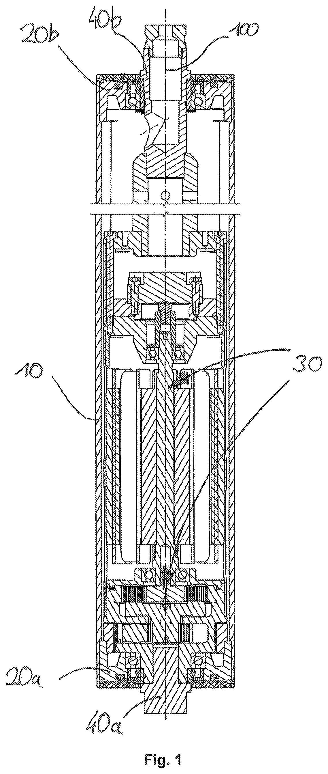
[0034]Referring first to FIG. 1, a drum motor is basically made up of a drum tube 10, into which a lid 20a, 20b is inserted at each end, preferably of the same design. The lids 20a, 20b, are torque-proof connected to the drum tube 10 by creating a frictional interference fit between the outer circumference of the lids 20a, 20b and the circumference of the drum tube 10. Instead of the frictional connection, torque transmission can also be realized by form-locking, material flow or mixed forms of this.
[0035]Inside the drum tube 10 there is a drive unit 30 consisting of an electric motor and a gearbox. The drive unit 30 generates a torque and a rotational movement between the drum tube 10 and two stub axles 40a, 40b, which are supported by roller bearings in the lids 20a, 20b. The stub axles 40a, 40b, protrude at the front side out of the respective lid 20a, 20b and can therefore be fixed in a frame which accommodates the drum motor. The drive unit 30 is supported torque-proof on the s...
PUM
| Property | Measurement | Unit |
|---|---|---|
| diameter | aaaaa | aaaaa |
| diameter | aaaaa | aaaaa |
| thickness | aaaaa | aaaaa |
Abstract
Description
Claims
Application Information