Supercharge Your Innovation With Domain-Expert AI Agents!

Red luminophor, LED device and method for making the LED device

a technology of led devices and luminophors, applied in the field of led, can solve the problems of low plant absorption rate of red light, low irradiation efficiency of blue led chips and red phosphors, complicated manufacturing process of led red light semiconductor chips, etc., and achieves less energy loss, less energy loss, and higher optical radiation power.

Active Publication Date: 2022-03-08
APT ELECTRONICS
View PDF13 Cites 0 Cited by
  • Summary
  • Abstract
  • Description
  • Claims
  • Application Information

AI Technical Summary

Benefits of technology

The solution provides higher optical radiation power with reduced energy loss and manufacturing costs, achieving comparable results to traditional red light LED semiconductor chips while improving irradiation efficiency and matching plant absorption needs.

Problems solved by technology

As the manufacture process for such LED red light semiconductor chip is complicated and costly, the LED red light semiconductor chip is typically replaced by a combination of blue LED chip and red phosphors.
Therefore, in general, the combination of the blue LED chip and the red phosphors features low irradiation efficiency and low plant absorption rate for red light.

Method used


Image

  • Red luminophor, LED device and method for making the LED device
  • Red luminophor, LED device and method for making the LED device

Examples


embodiment 1

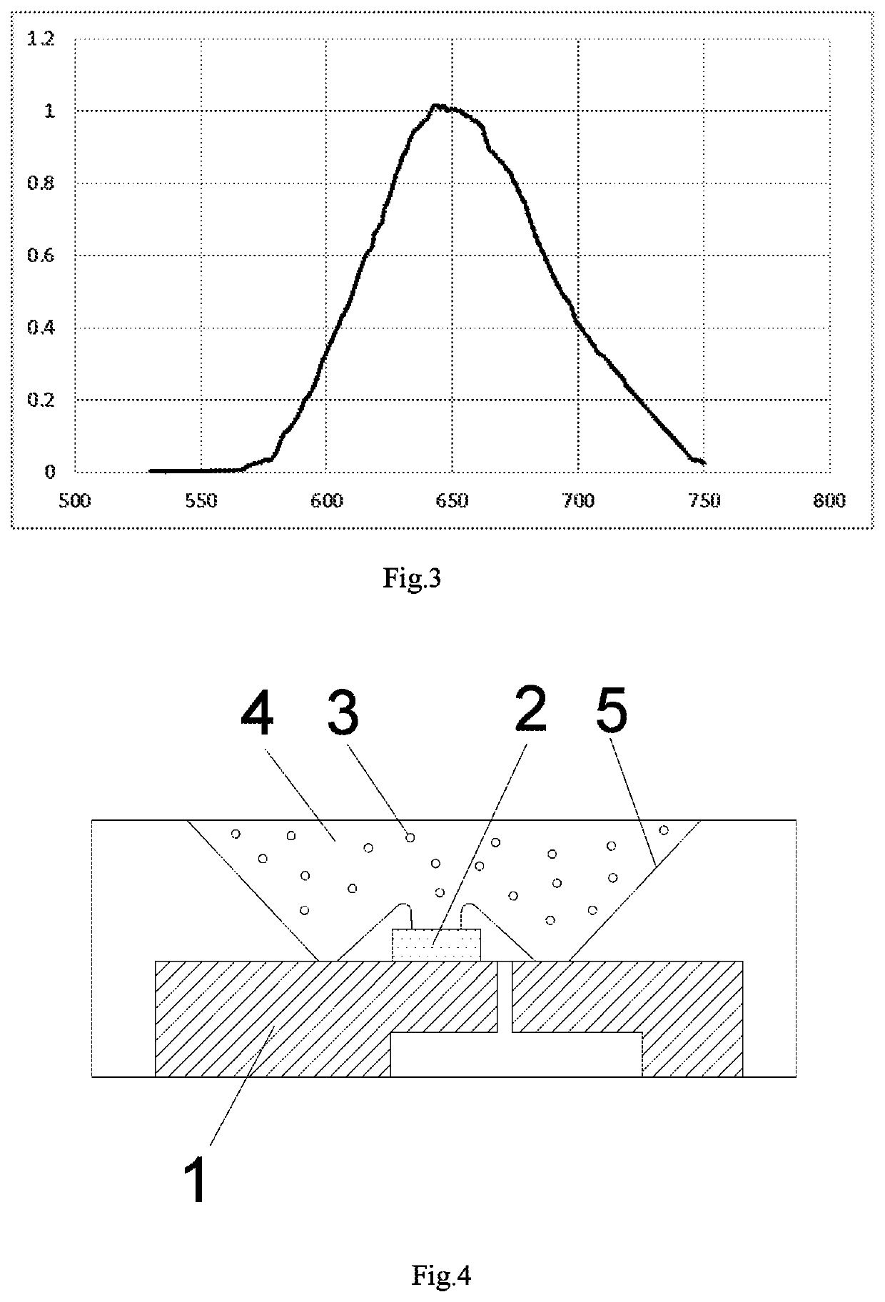
[0039]As shown in FIG. 4, a LED device includes a carrier 1, a blue LED 2, red luminophors 3, a transparent sealant 4 and electrical connection lead. The red luminophors 3 are dispersed in the transparent sealant 4, and the transparent sealant 4 covers the blue LED 2. The electrical connection lead connects the blue LED 2 and the carrier 1. Wherein, the carrier 1 is a ceramic substrate, the red luminophors 3 are a combination of SrLiAl3N4:Eu2+ and CaLiAl3N4:Eu2+, the transparent sealant 4 is epoxy resin, and the electrical connection lead is copper wire.

embodiment 2

[0040]As shown in FIG. 4, a LED device includes a carrier 1, a blue LED 2, red luminophors 3, a transparent sealant 4 and electrical connection lead. The red luminophors 3 are dispersed in the transparent sealant 4, and the transparent sealant 4 covers the blue LED 2. The electrical connection lead connects the blue LED 2 and the carrier 1. Wherein, the carrier 1 is a metal substrate without any leads, the red luminophors 3 are a combination of SrLiAl3N4:Eu2+ and Sr4LiAl11N14:Eu2+, the transparent sealant 4 is acrylic resin, and the electrical connection lead is silver wire.

embodiment 3

[0041]As shown in FIG. 4, a LED device includes a carrier 1, a blue LED 2, red luminophors 3, a transparent sealant 4, and electrical connection lead. The red luminophors 3 are dispersed in the transparent sealant 4, and the transparent sealant 4 covers the blue LED 2. The electrical connection lead connects the blue LED 2 and the carrier 1. Wherein, the carrier 1 is a metal substrate without any leads, the red luminophors 3 are a combination of Sr4LiAl11N14:Eu2+ and Li2Ca2(Mg2Si2N6):Eu2+, the transparent sealant 4 is acrylic resin, the electrical connection lead is copper wire.


PUM

PropertyMeasurementUnit
FWHMaaaaaaaaaa
FWHMaaaaaaaaaa
FWHMaaaaaaaaaa

Abstract

A red luminophor, LED device and method for making the LED device. The red luminophor includes one or more materials selected from SrLiAl3N4:Eu2+, CaLiAl3N4:Eu2+, Sr4LiAl11N14:Eu2+ and Li2Ca2(Mg2Si2N6):Eu2+. The LED device includes the red luminophor. The method for making the LED device includes preparing a carrier; installing a blue LED onto the carrier; mixing the red luminophors and the transparent sealant to form a mixture; dispensing the mixture on the blue LED and the carrier to form an integration; and heating and curing the integration. The red luminophor has continuous light radiation in the wavelength range of 600 nm-750 nm, with the emission peak at 650-680 nm and the FWHM of less than 90 nm. Its emission light intensity at the wavelength of 730 nm is not less than 30% of its maximum emission light intensity, which matches the absorption needs of phytochrome of plant.

Description

CROSS-REFERENCE TO RELATED APPLICATIONS[0001]This application claims priority to PCT Application No. PCT / CN2018 / 124161, having a filing date of Dec. 27, 2018, which is based on Chinese Application No. 201811486520.2, having a filing date of Dec. 6, 2018, the entire content of which is hereby incorporated by reference.FIELD OF TECHNOLOGY[0002]The following relates to a field of LED, in particular, a red luminophor, LED device and method for making the LED device.BACKGROUND[0003]Phytochromes in plants are sensitive to red light and far-red light, which contribute the plant's ability to germinate, such that the timing of flowering in plants can be regulated by adjusting the wavelength of red light in order to artificially control the breeding of plants. LED red light semiconductor chip is an important component of plant-lighting LED device, and is made from quaternary compound of AlInGaP system. The wavelength of red light emitted by the LED red light semiconductor chip can be adjusted...

Claims


Application Information

Patent Timeline
Patent Type & Authority Patents(United States)
IPC IPC(8): H01L33/50A01G7/04H01L33/56
CPCH01L33/507A01G7/045H01L33/502H01L33/56H01L2933/0041C09K11/7734C09K11/0883Y02P60/14
Inventor WAN, CHUIMINGZENG, ZHAOMINGYAO, SHUGUANGKEUNG, CHIWINGLIU, RU-SHIXIAO, GUOWEI DAVID
Owner APT ELECTRONICS
Features
  • R&D
  • Intellectual Property
  • Life Sciences
  • Materials
  • Tech Scout
  • Unparalleled Data Quality
  • Higher Quality Content
  • 60% Fewer Hallucinations
Learn More