Electrically conductive PTC ink with double switching temperatures and applications thereof in flexible double-switching heaters

Active Publication Date: 2022-04-12
LMS CONSULTING GRP LLC
View PDF8 Cites 0 Cited by
  • Summary
  • Abstract
  • Description
  • Claims
  • Application Information

AI Technical Summary

Benefits of technology

The present invention is related to a double-switching heater that has two layers of resistive material, each with its own temperature range. The heater can be deposited on a flexible or rigid substrate, and can be used in various applications such as flooring materials, fluid pipes, and molds. The heater demonstrates temperature fluctuations of 5 degrees at an operating temperature of 48°C, and has substantially no degradation over multiple operating cycles. The invention also includes a sensor and feedback loop to regulate operating temperature. The technical effects of the invention include improved heating efficiency, precise temperature control, and durability.

Problems solved by technology

When the temperature is above the melting point (Tm) or softening point (Ts) of the polymer, the polymeric PTC composition will turn unstable, which usually results in the NTC behaviour.

Method used


Image

  • Electrically conductive PTC ink with double switching temperatures and applications thereof in flexible double-switching heaters
  • Electrically conductive PTC ink with double switching temperatures and applications thereof in flexible double-switching heaters
  • Electrically conductive PTC ink with double switching temperatures and applications thereof in flexible double-switching heaters

Examples


example 1

[0137]The PTC ink and film were made following the typical procedure described above. The polymer resin-1, polymer resin-2, carbon black, solvent, dispersing additive, and rheology additive used in this Example, Example 2 and Example 3 are respectively polyethylene glycols (Carbowax 1450 from Dow Chemicals) with a melting point ranging from 42−46° C., polyvinylidene fluoride (PVDF) (Solef460 from Solvay) with a melting point of 155-160° C., carbon black REGAL 350R, NMP, BYK-220S, and BYK-410, and their contents in the PTC compositions are listed in TABLE-1.

[0138]In order to test the PTC ink for dispersion and resistivity, the PTC ink compositions of Examples 1, 2 and 3 were screen-printed onto polyester film to produce four strips, each strip having dimensions of approximately 1 cm by 10 cm. Silver contacts were applied to both ends of each strip in order to measure resistance and experimental error. In addition, a 5 cm by 5 cm square was printed to evaluate dispersion and uniformit...

example 2

[0139]The conditions were used as Example 1, but more polymer solution was added into the system. The resistivity at 25° C. of the PTC film from this example is 8.0 Kohm / sq. FIG. 8 shows the temperature-resistance curves generated using this Example.

example 3

[0140]The same conditions were used as Examples 1 and 2, but more polymer solution was added into the system. The resistivity at 25° C. of the PTC film from this example is 15.0 Kohm / sq. FIG. 8 shows the temperature-resistance curves generated using this Example.

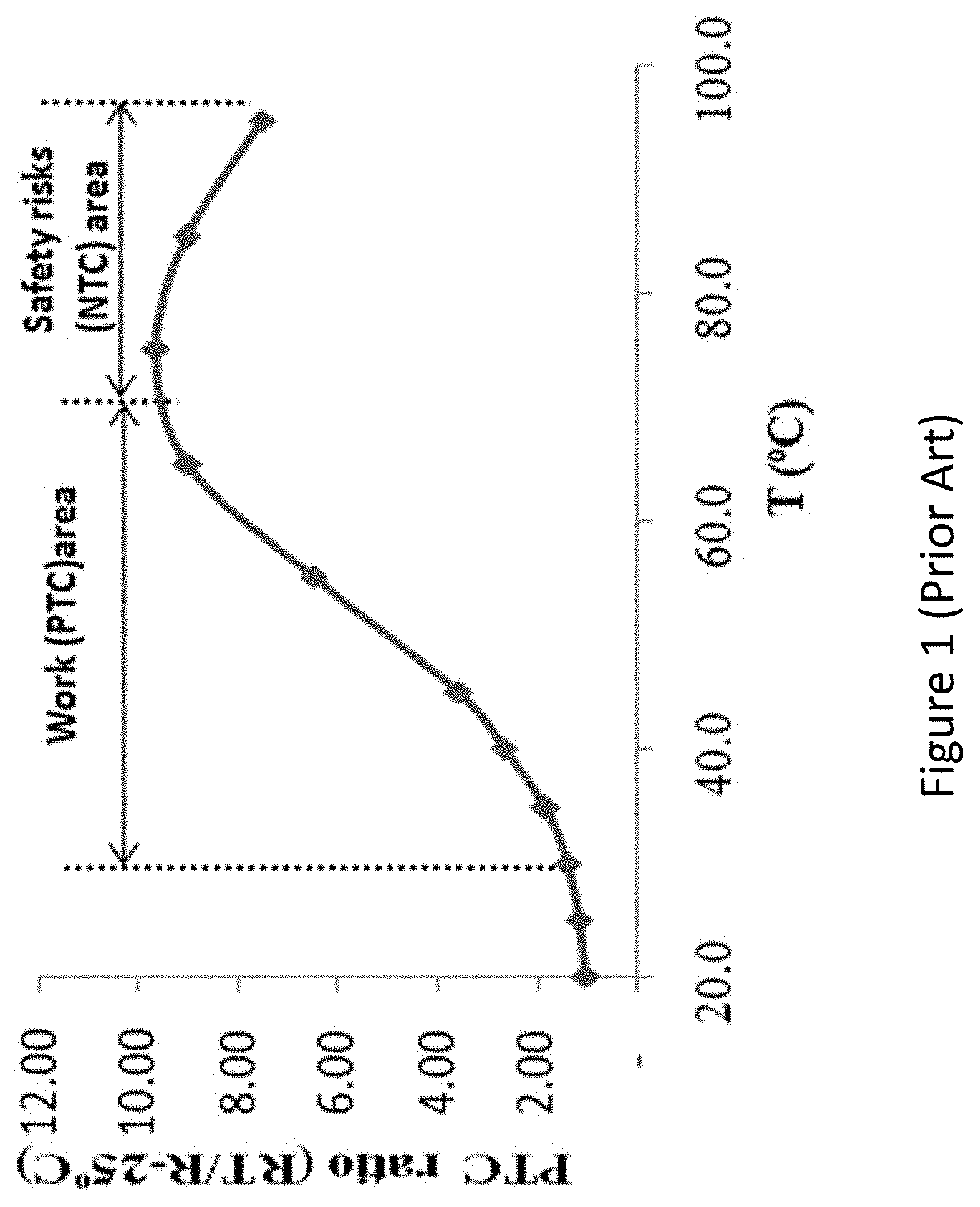
[0141]As shown in FIG. 8, the PTC ink of the present invention presents good PTC effect, at 60° C., the PTC ratio RT / R-25 is higher than 10, the value of sample 3 is even higher than 20. As the temperature is raised further, no NTC effect appear, it still present good PTC effect, at 120° C., the PTC ratio RT / R-25 is higher than 30, the value of sample 3 is even higher than 50. When the present PTC ink is applied in a self-regulating heating element with low regulated temperatures (<70° C.), the safety risks area is completely eliminated.


PUM


Abstract

An article comprising a double-switching heater that comprises a double-switching PTC ink deposited on a flexible substrate to form one or more resistors. The double-switching PTC ink comprises a first resin and a second resin; the first resin provides a first PTC effect within a first temperature range (T1, T2); the second resin provides a second PTC effect within a second temperature range (T3, T4), where T3≥T2; the first resin has an NTC effect above the first temperature range; the second PTC effect is greater than the first PTC effect; and the second PTC effect overlaps with, and is greater than, the NTC effect of the first resin. The substrate can be either thermal polyurethane, nylon or a polyester blend.

Description

CROSS-REFERENCE TO RELATED APPLICATIONS[0001]This application is a continuation-in-part of U.S. patent application Ser. No. 16 / 454,570, filed Jun. 27, 2019, now allowed, which is a divisional of U.S. patent application Ser. No. 15 / 441,396, filed Feb. 24, 2017, now allowed, which is a continuation-in-part of U.S. patent application Ser. No. 15 / 143,524, filed Apr. 30, 2016, now U.S. Pat. No. 10,077,372, which is a continuation-in-part of U.S. patent application Ser. No. 14 / 120,638, filed Jun. 12, 2014, and which claims the benefit of U.S. Provisional Application No. 62 / 389,396, filed Feb. 24, 2016, each of which is hereby incorporated by reference herein in its entirety.[0002]U.S. patent application Ser. No. 15 / 441,396, filed Feb. 24, 2017, is also a continuation-in-part of U.S. patent application Ser. No. 14 / 120,638, filed Jun. 12, 2014, and claims the benefit of U.S. Provisional Application No. 62 / 389,396, filed Feb. 24, 2016, each of which is hereby incorporated by reference herein...

Claims


Application Information

Patent Timeline
IPC IPC(8): H01C7/02C09D11/108C09D11/107C09D11/106C09D11/104C09D11/037H05B3/12F25C1/22A41D13/005E04C2/52C09D11/10H01L49/02H01C7/04C09D11/52F25C5/08
CPCH01C7/02A41D13/0051C09D11/037C09D11/10C09D11/104C09D11/106C09D11/107C09D11/108C09D11/52E04C2/525F25C1/22H01C7/027H01C7/028H01C7/04H01L28/20H05B3/12F25C5/08H05B2203/017H05B2203/019H05B2203/02H05B2203/026
Inventor XIAO, SHUYONGSISLER, LEE M.ABBOTT, RICHARD C.
Owner LMS CONSULTING GRP LLC
Why Eureka
Try Eureka