Liquid rocket engine cross impinged propellant injection

a technology of propellant injection and liquid rocket engine, which is applied in the direction of machines/engines, cosmonautic vehicles, lighting and heating apparatus, etc. it can solve the problems of high temperature fuel located proximate the combustion chamber that does not mix efficiently with lower temperature fuel, turbopump size, propellant consumption, etc., to reduce the size of the turbopump, reduce the weight and propellant consumption, and increase the weight of the payload.

Active Publication Date: 2022-05-17
FIREFLY IP CO LLC
View PDF40 Cites 0 Cited by
  • Summary
  • Abstract
  • Description
  • Claims
  • Application Information

AI Technical Summary

Benefits of technology

[0014]The present invention provides a number of important technical advantages. One example of an important technical advantage is an increased payload weight supported by a liquid rocket engine due to reduced turbopump size, weight and propellant consumption. Cooling channels integrated in the combustion chamber wall improve heat transfer from the combustion chamber wall by increasing the unsteadiness of boundary layers in a propellant flow that passes through the cooling channels. Improved thermal transfer through the propellant flow reduces flow rate and pressurization of propellant through the cooling channels needed to maintain combustion chamber walls within a desired temperatures constraint, such as not greater than one-third the melting temperature of the combustion chamber material. As a result, the payload weight supported by the liquid rocket engine for a given orbit is increased due to the decreased weight in propellant and equipment need to achieve the orbit.
[0015]Another example of an important technical advantage is that fuel and oxygen injection into a combustion chamber are supported with a simplified and cost efficient construction. For example, fuel and oxygen injection ports are drilled through material without coupling specialized injector structures in the combustion chamber. Combustion location and propellant mixing are defined with cross impinged injection streams that form one or more vortexes within the combustion chamber. Vortex flow separates combustion zones having separate fuel mixture ratios and flow patterns. Within the vortex, oxygen-rich flow centrifugally mixes with a part of the injected fuel to encourage full and efficient combustion in the vortex. As oxygen flow extends out of the vortex and into an axial flow towards the nozzle for exhaust, addition combustion is encouraged with a central portion of the combustion chamber. Oxygen flow reduces thermal transfer to the combustion chamber headend and the oxygen injector to provide thermal management without expensive and complex injector structures.

Problems solved by technology

The boundary layers stratify temperatures across the flow so that higher temperature fuel located proximate the combustion chamber does not mix efficiently with lower temperature fuel of the rest of the flow.
Increased turbopump size, weight and propellant consumption tend to decrease rocket payload weight.
Inadequate pressurization of propellant within cooling channels can lead to catastrophic failure since vaporization of a fluid within a cooling channel substantially decreases thermal transfer properties.
Incomplete mixing of propellant, incomplete burning of propellant and uneven propellant flow through the combustion chamber can result in hot spots forming at the combustion chamber wall, which may lead to catastrophic failure.
One difficulty with coaxial, swirl and oblique jet injection methods is that propellant strands can form in the combustion chamber having a rich combustion due to an excess of fuel or a lean combustion due to an oxidation excess.
Propellant strand formation impairs combustion efficiency by leaving propellant unconsumed and may also lead to hot-gas corrosion or spot-type excess temperatures, which can destroy the combustion chamber wall.
If thermally decomposable fuel is involved, strands with an excess of fuel may lead to local pressure peaks, which can cause high-frequency combustion instabilities.
Injection heads tend to include interfaces between fuel and oxygen made by complicated and expensive manufacture techniques to ensure no contact between the fuel and oxygen.
For example, injectors are often manufactured with expensive heat resistant material to withstand high temperatures generated proximate propellant combustion.

Method used


Image

  • Liquid rocket engine cross impinged propellant injection
  • Liquid rocket engine cross impinged propellant injection
  • Liquid rocket engine cross impinged propellant injection

Examples


Embodiment Construction

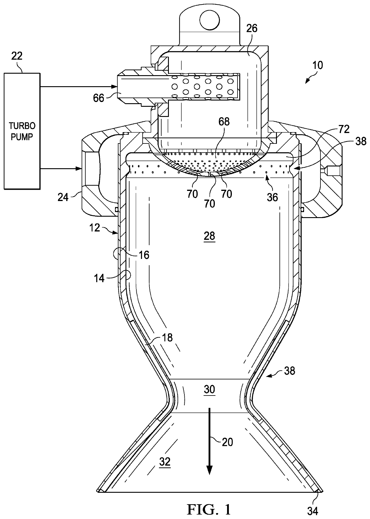
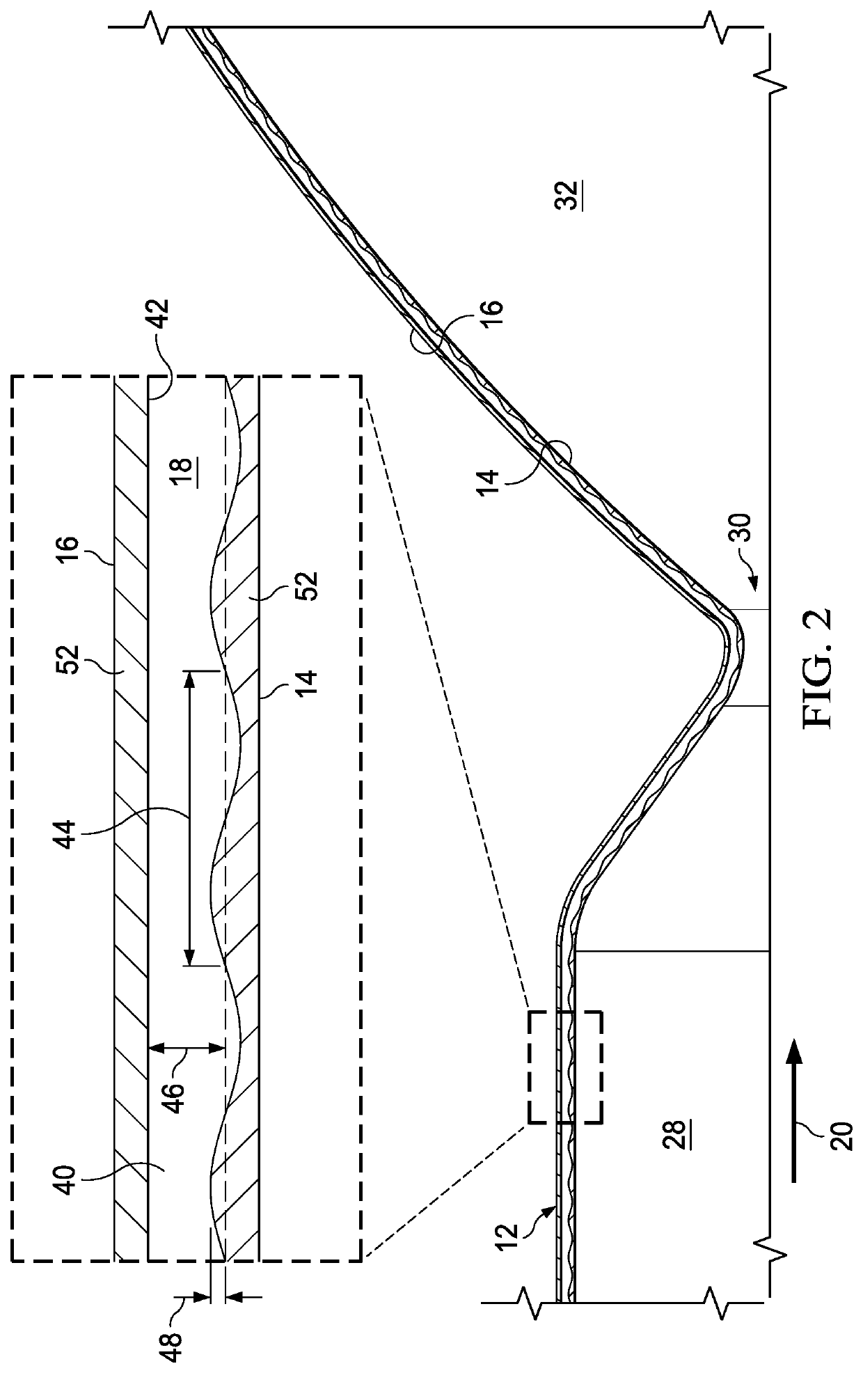
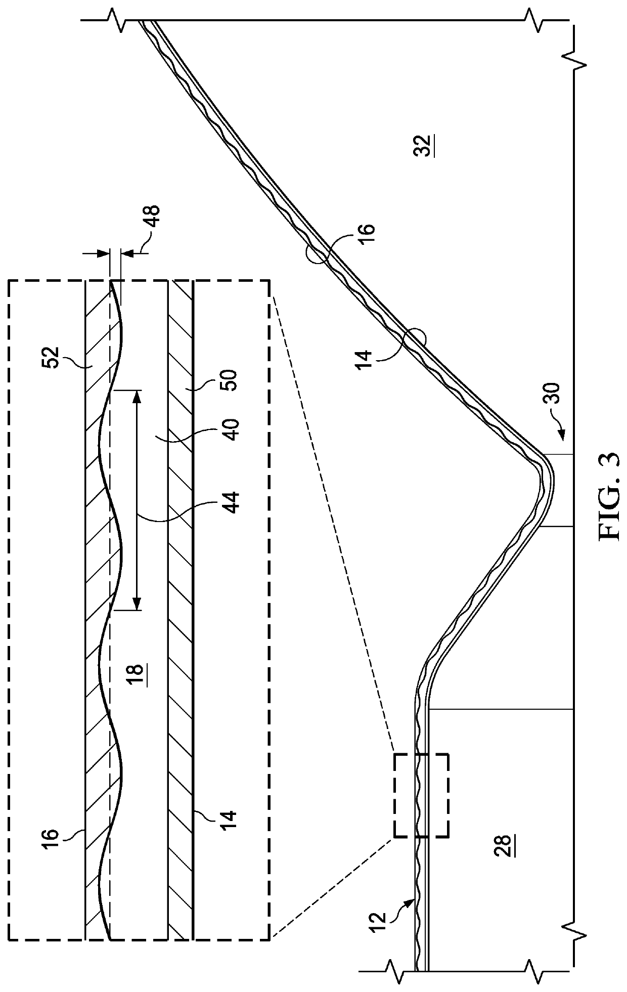
[0028]Variation in depth of cooling channels integrated in a liquid rocket engine thruster body mixes thermally-stratified layers of propellant flow passing through the cooling channels to improve thermal rejection from the thruster body compared against conventional cooling channels. For example, variations in cooling channel depth includes repeated continuous patterns, such as wavy cooling channels having periodical variable depth of a sine wave form. In one example embodiment, wavelength and amplitude of a cooling channel surface are proportional to an average cooling channel depth. A sinusoidal wave surface shape along a cooling channel destroys coolant stratification by moving hot layers from lateral surfaces near a thruster body interior surface and mixing the hot layer of coolant with cooler layers so that the bulk temperature of the coolant is made uniform and thermal transfer from the thruster body interior surface to the coolant increases. The overall effect is to improve ...


PUM


Abstract

A liquid rocket engine cools a thruster body by pumping propellant through cooling channels integrated in the thruster body between internal and external surfaces. One or more of the cooling channel surfaces has a variable depth along a thrust axis to mix propellant flow and destroy thermal stratification, such as a depth that varies with a repeated contiguous sinusoidal form along the thrust axis. Fuel passed through the cooling channels injects from the combustion chamber wall towards a central portion of the combustion chamber to cross impinge with oxygen injected at the combustion chamber head so that a toroidal vortex forms to enhance propellant mixing.

Description

STATEMENT REGARDING FEDERALLY SPONSORED RESEARCH OR DEVELOPMENT[0001]This invention was made with Government support under Agreement No. HR0011-16-9-0011, awarded by DARPA. The Government has certain rights in the invention.BACKGROUND OF THE INVENTIONField of the Invention[0002]The present invention relates in general to the field of liquid rocket propulsion, and more particularly to liquid rocket engine cross impinged propellant injection.Description of the Related Art[0003]Liquid rocket engines generate thrust by burning fuel, such as kerosene, mixed with liquid oxygen in a combustion chamber at extremely high temperatures and pressures, such as 3500 degrees Kelvin and 1,000 pounds per square inch (psi). Exhausting the hot gas from the combustion chamber through a throat and out a nozzle produces a supersonic airflow that generates thrust. Generally, to lift off the ground, thrust generated by the rocket exhaust must exceed the weight of the rocket, including the rocket payload (i...

Claims


Application Information

Patent Timeline
Patent Type & Authority Patents(United States)
IPC IPC(8): F02K9/52F23L7/00F02K9/42F02K9/64F02K9/62B64G1/00F02K9/97
CPCF02K9/52B64G1/00F02K9/42F02K9/425F02K9/62F02K9/64F02K9/972F23L7/007F05D2260/22141Y02E20/34
Inventor BORISSOV, ANATOLI ALIMPIEVICHMARKUSIC, THOMAS EDWARD
Owner FIREFLY IP CO LLC
Why Eureka
Try Eureka