Quadrature error correction for radio transceivers

a radio transceiver and quadrature error technology, applied in the direction of low noise amplifiers, gain control, digital transmission, etc., can solve the problems of coarse correction, limited resolution of capacitor settings, degraded accuracy, etc., to reduce quadrature error, enhance performance, and reduce the effect of quadrature error

Active Publication Date: 2022-06-28
ANALOG DEVICES INC
View PDF76 Cites 1 Cited by
  • Summary
  • Abstract
  • Description
  • Claims
  • Application Information

AI Technical Summary

Benefits of technology

[0004]A transmit or receive channel of an RF communication system can be calibrated to compensate for impairments, thereby enhancing the RF communication system's performance.SUMMARY OF THE DISCLOSURE
[0005]Quadrature error correction (QEC) for radio transceivers are provided herein. In certain embodiments, a transceiver includes an in-phase (I) signal path including a first controllable amplifier coupled to a first data converter, and a quadrature-phase (Q) signal path including a second controllable amplifier coupled to a second data converter. The transceiver further includes a QEC circuit operable to correct for a quadrature error between the I signal path and the Q signal path by adjusting a gain of the first controllable amplifier and / or a gain of the second controllable amplifier. By implementing the transceiver in this manner, quadrature error is reduced. Moreover such a QEC scheme provides enhanced performance relative to an implementation in which only feedback capacitance settings (for instance, an amplifier feedback capacitor setting) are adjusted for QEC. For example, capacitance settings can have limited resolution and / or degraded accuracy in the presence of parasitic capacitances, and thus provide only a coarse correction.

Problems solved by technology

For example, capacitance settings can have limited resolution and / or degraded accuracy in the presence of parasitic capacitances, and thus provide only a coarse correction.

Method used


Image

  • Quadrature error correction for radio transceivers
  • Quadrature error correction for radio transceivers
  • Quadrature error correction for radio transceivers

Examples


Embodiment Construction

[0021]The following detailed description of embodiments presents various descriptions of specific embodiments of the invention. However, the invention can be embodied in a multitude of different ways. In this description, reference is made to the drawings where like reference numerals may indicate identical or functionally similar elements. It will be understood that elements illustrated in the figures are not necessarily drawn to scale. Moreover, it will be understood that certain embodiments can include more elements than illustrated in a drawing and / or a subset of the elements illustrated in a drawing. Further, some embodiments can incorporate any suitable combination of features from two or more drawings.

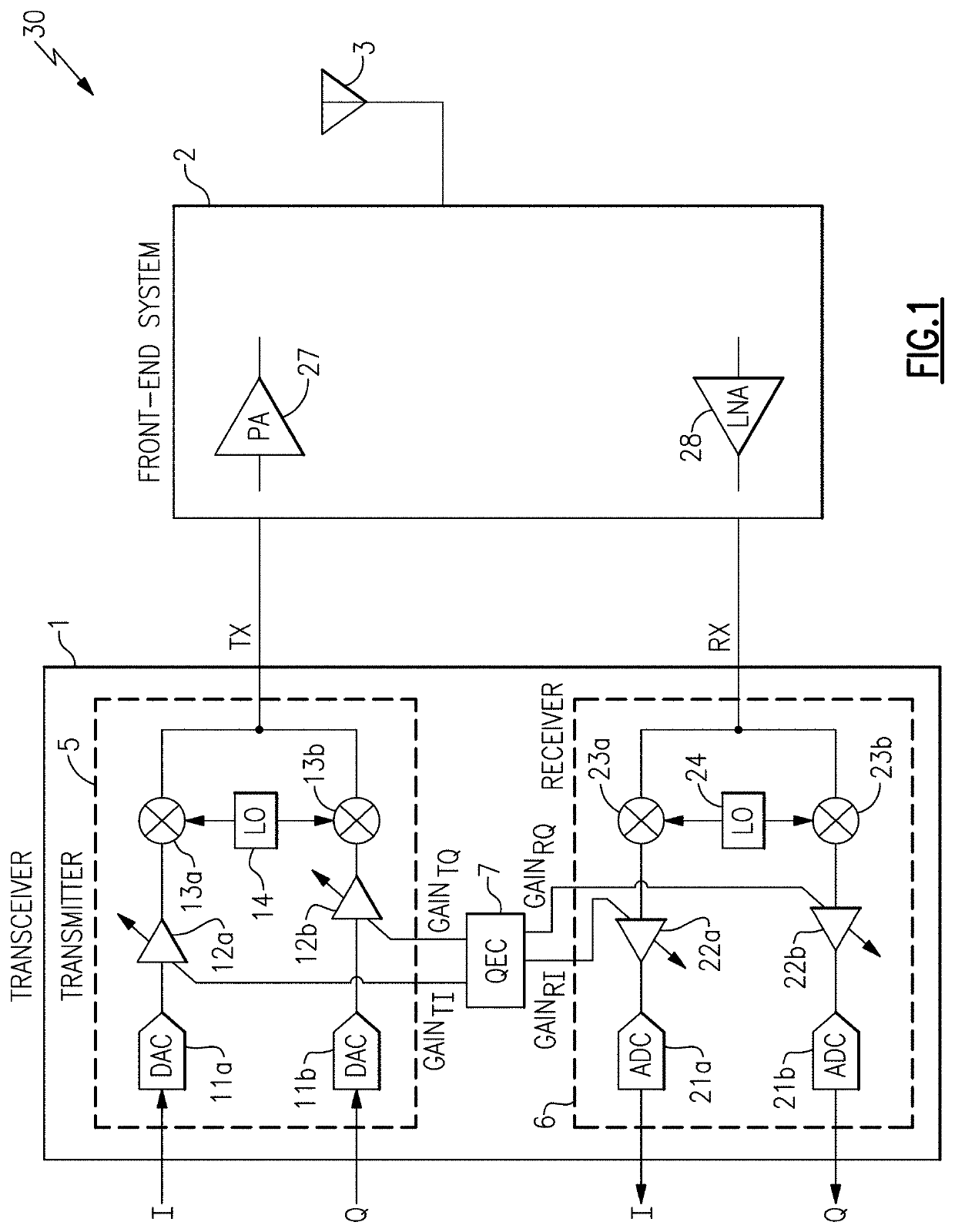
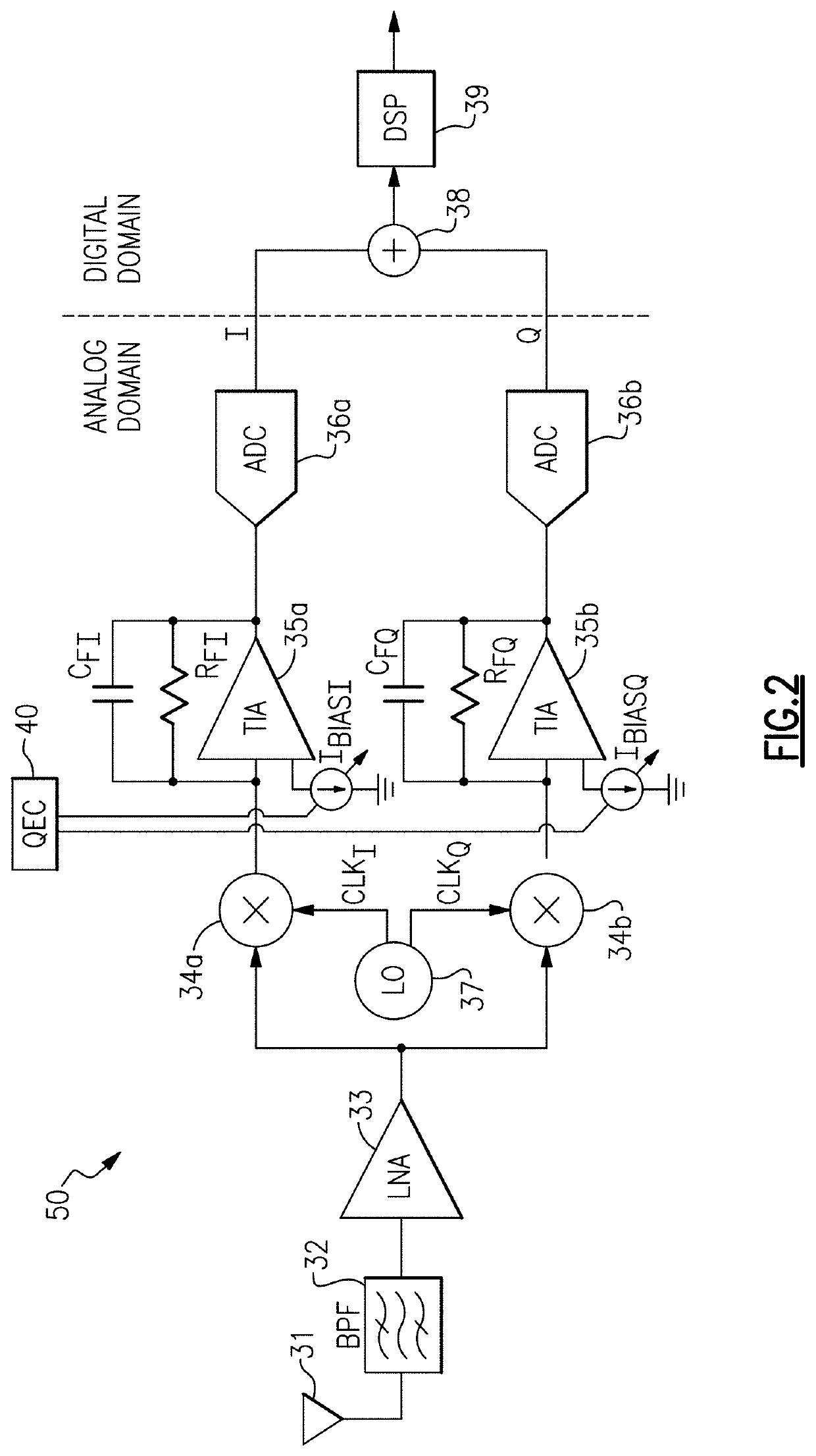
[0022]A radio frequency (RF) communication system, such as a direct conversion quadrature radio, can suffer from a variety of impairments. Absent calibration, the impairments can lead to transmit errors, receive errors, and / or other performance degradation.

[0023]For example, a d...


PUM


Abstract

Quadrature error correction (QEC) for radio transceivers are provided herein. In certain embodiments, a transceiver includes an in-phase (I) signal path including a first controllable amplifier coupled to a first data converter, and a quadrature-phase (Q) signal path including a second controllable amplifier coupled to a second data converter. The transceiver further includes a QEC circuit operable to correct for a quadrature error between the I signal path and the Q signal path by adjusting a gain of the first controllable amplifier and / or a gain of the second controllable amplifier.

Description

CROSS-REFERENCE TO RELATED APPLICATIONS[0001]The present application claims priority to U.S. Provisional Patent Application No. 63 / 092,740, filed Oct. 16, 2020, and titled “QUADRATURE ERROR CORRECTION FOR RADIO TRANSCEIVERS,” the entirety of which is hereby incorporated herein by reference.FIELD OF THE DISCLOSURE[0002]Embodiments of the invention relate to electronic systems, and more particularly to, quadrature error correction in radio frequency communication systems.DESCRIPTION OF THE RELATED TECHNOLOGY[0003]A radio transceiver can be used in a wide variety of radio frequency (RF) communication systems. For example, transceivers can be included in base stations or mobile devices to transmit and receive signals associated with a wide variety of communications standards, including, for example, cellular and / or wireless local area network (WLAN) standards. Transceivers can also be used in radar systems, instrumentation, industrial electronics, military electronics, laptop computers,...

Claims


Application Information

Patent Timeline
Patent Type & Authority Patents(United States)
IPC IPC(8): H03H7/30H03H7/40H03K5/159H04L27/00H04B1/38H03F3/45H03G3/30
CPCH04L27/0014H03F3/45475H03G3/3036H04B1/38H03F2200/129H03F2200/294H03F2200/451H03F2203/45116H03G2201/103H03G2201/307H04L2027/0016H03F1/083H03F3/19H03F3/245H03F2200/165H03F2203/45526H03G3/001H03G3/008H03G3/3078H03G1/0094
Inventor ABDEL FATTAH, OMAR A SSTEINBRECHER, CHRISTOPH M.
Owner ANALOG DEVICES INC
Why Eureka
Try Eureka