Thin aerogel materials

a technology of aerogels and materials, applied in the direction of cell components, jackets/cases, cell maintenance/service, etc., can solve the problems of significant pore collapse and gel shrinkage, aerogels can be extremely brittle and difficult to handle, and it is difficult to incorporate aerogels into thermal batteries

Active Publication Date: 2022-07-05
ASPEN AEROGELS INC
View PDF78 Cites 3 Cited by
  • Summary
  • Abstract
  • Description
  • Claims
  • Application Information

AI Technical Summary

Benefits of technology

[0009]The present invention provides a uniformly thin, fiber-reinforced aerogel insulation material which can be used in thermal battery applications. The fiber-reinforced aerogel insulation material is highly durable, flexible, and has a thermal performance that exceeds the insulation materials currently used in thermal battery applications. The fiber-reinforced aerogel insulation material can be as thin as 1 mm or less, and can have a thickness variation as low as 3% or less.
[0013]The incorporation of the reinforced aerogel material into the thermal battery can result in an improved battery performance for the thermal battery, with the increase in performance resulting primarily from the incorporation of the reinforced aerogel material into the thermal battery. In one embodiment, the improved battery performance for the thermal battery, when measured at about −54° C., can be: i) an improved battery performance for 1V run time of up to about 300%; ii) an improved battery performance for 16V run time of up to about 250%; or iii) an improved battery performance for 22V run time of up to about 200%. In another embodiment, the improved battery performance for the thermal battery, when measured at about 21° C., can be: i) an improved battery performance for 1V run time of up to about 215%; ii) an improved battery performance for 16V run time of up to about 200%; or iii) an improved battery performance for 22V run time of up to about 175%.

Problems solved by technology

A primary challenge in designing thermal batteries is heat management.
These innovative processing and drying techniques can reduce the capillary pressure and surface tension generated by evaporation in small pores, which often causes significant pore collapse and gel shrinkage during a traditional solvent extraction process.
However, aerogels can also be extremely brittle and difficult to handle.
It is particularly difficult to incorporate aerogels into thermal batteries due to significant design and space limitations associated with thermal batteries.

Method used


Image

  • Thin aerogel materials
  • Thin aerogel materials
  • Thin aerogel materials

Examples


example 1

Casting Table

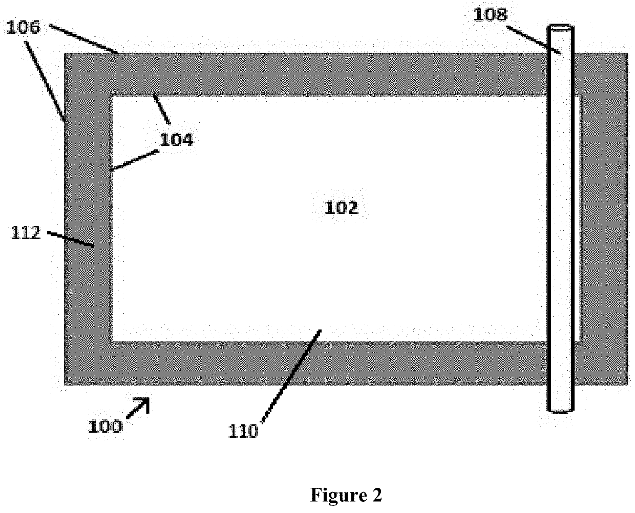
[0104]FIG. 2 illustrates a casting table 100 which was used for the production of thin sheets of Fiber-Reinforced Aerogel Materials. A 4 ft×6 ft sheet of PETG (polyethylene terephthalate glycol-modified) having a thickness of 0.078 inches (˜2 mm) was placed onto a Teflon-covered 4 ft×6 ft table. A 3 ft×5 ft rectangle of PETG material was cut and removed from the interior of the PETG sheet. The remaining PETG material provided thickness control during the subsequent casting of the aerogel material. The thickness of the PETG material was chosen to provide a final cast thickness of 0.070 inches (˜1.75 mm) for the aerogel insulation material.

[0105]The resulting casting table 100 comprised a 3 ft×5 ft casting area 102, enclosed by a rectangular PETG casting frame which was 0.078 inches thick (˜2 mm), and which had a perimeter of 4 ft×6 ft on the exterior edges 106, a perimeter of 3 ft×5 ft on the interior edges 104, and a uniform 1 ft width from the outer edges 106 to the in...

example 2

Preparation of Fiber-Reinforced Aerogel Materials

[0106]FIGS. 1a-1h illustrate a method for producing thin aerogel materials of a uniform thickness. A sol-gel solution with a target density of 0.06 g / cc was prepared by hydrolyzing tetraethyl orthosilicate (TEOS) and methyltriethoxy silane (MTES) in the presence of acid. SiC F1200 Black (Carborex© F1200, Washington Mills) was added to the sol-gel solution.

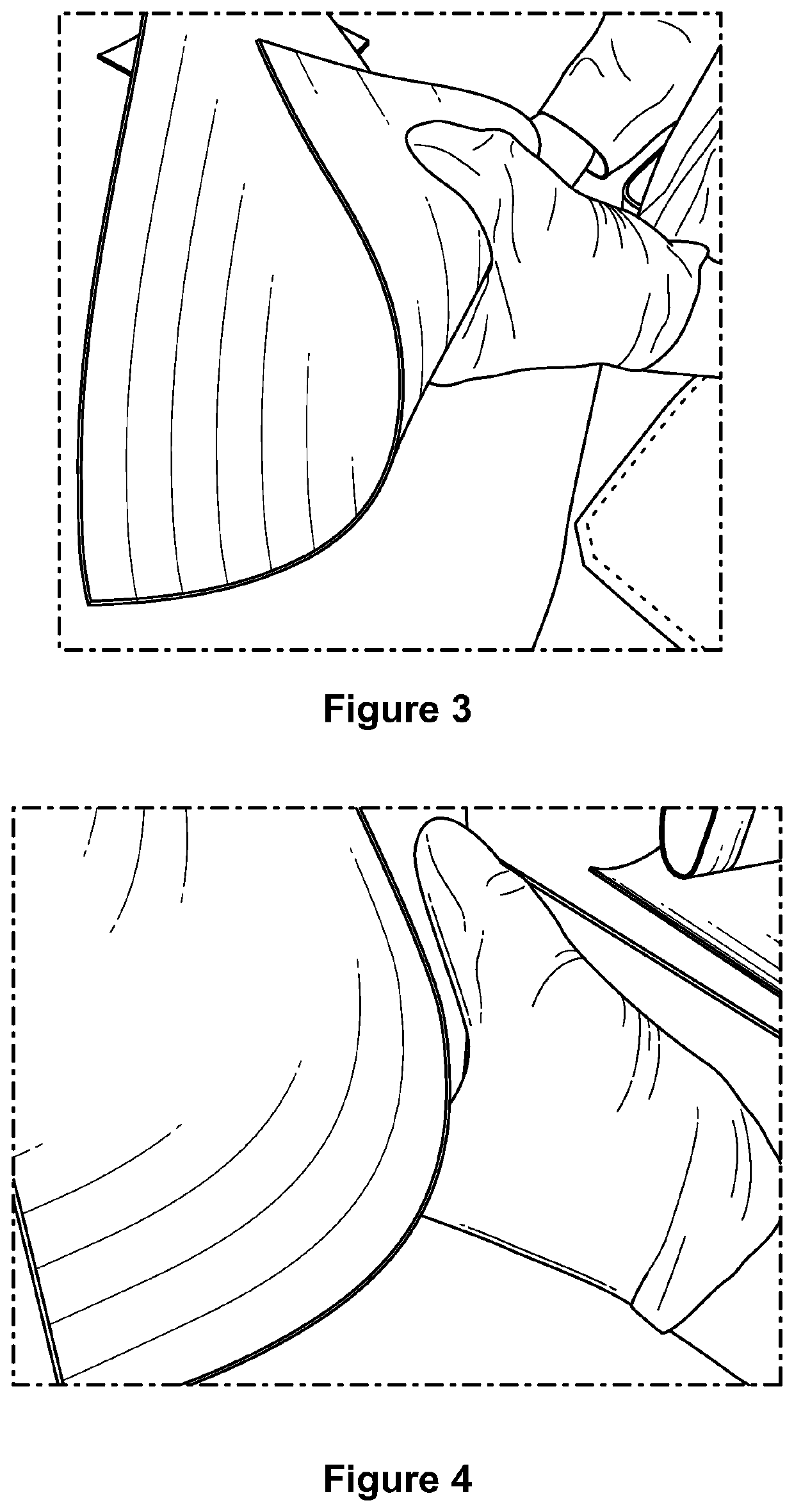
[0107]A lofty fiber batting (Quartzel©), Saint-Gobain Quartz) was placed into the casting area of the casting table of Example 1 (FIG. 1a). Ammonia was added to the sol-gel solution to initiate gelation. The sol-gel solution was then applied over a large portion of the batting material (FIGS. 1c and 1d). A nonporous Teflon sheet was placed over the casting table to minimize loss of ammonia during the casting process (FIG. 1e).

[0108]While the sol-gel solution was still in a substantially fluid state, the solution was spread throughout the batting using a roller. A roller bar was place...

example 3

Thickness Testing

[0112]A sheet of aerogel material from example 2 was cut into 8 in×8 in coupons for testing (FIG. 1h). Sixteen thickness measurements were made on each of eighteen different coupons (for a total of 288 measurements) using a hand-held drop-gauge. These measurements were used to determine the overall thickness variation in a composite sheet, as well as product yield (based on thickness).

[0113]FIG. 5 shows the average thickness measurements for all 18 coupons, presented along with the respective variation percentages. All coupons exhibited thickness variation below 7%. At 100% yield, the overall average thickness was 0.0759″ with 4.6% variation. Coupons prepared by this method demonstrated good particle dispersion and low thickness variation.


PUM

PropertyMeasurementUnit
thicknessaaaaaaaaaa
thicknessaaaaaaaaaa
thicknessaaaaaaaaaa

Abstract

The present invention provides a fiber-reinforced aerogel material which can be used as insulation in thermal battery applications. The fiber-reinforced aerogel material is highly durable, flexible, and has a thermal performance that exceeds the insulation materials currently used in thermal battery applications. The fiber-reinforced aerogel insulation material can be as thin as 1 mm less, and can have a thickness variation as low as 2% or less. Also provided is a method for improving the performance of a thermal battery by incorporating a reinforced aerogel material into the thermal battery. Further provided is a casting method for producing thin fiber-reinforced aerogel materials.

Description

REFERENCE TO PRIOR FILED APPLICATIONS[0001]This application claims the benefit of U.S. Provisional Application 62 / 015,757 filed Jun. 23, 2014 under 35 U.S.C. § 119(e); which application is incorporated by reference herein in its entirety.STATEMENT OF GOVERNMENT SUPPORT[0002]This invention was made with Government support under Contract HQ0147-12-C-0012 awarded by the Missile Defense Agency of the Department of Defense. The Government has certain rights in this invention.BACKGROUND[0003]Thermal batteries are batteries that employ inorganic salt electrolytes as barrier agents. Most thermal batteries are composed of a series of thermal cells, each having an anode, an electrolyte barrier, a cathode, and a pyrotechnic heating mass. The electrolyte barrier functions as a separator between the anode and the cathode, and is a relatively non-conductive solid at ambient temperatures. The thermal cells thus remain completely inert while the battery is stored at normal temperatures and the elec...

Claims


Application Information

Patent Timeline
Patent Type & Authority Patents(United States)
IPC IPC(8): H01M50/138B01J13/00H01M50/116H01M6/36H01M6/50H01M50/117H01M50/121H01M50/122H01M50/124H01M50/131H01M50/133
CPCH01M50/138B01J13/0091H01M6/36H01M6/5072H01M50/116H01M50/133H01M50/121H01M50/124H01M50/117H01M50/122H01M50/131Y02E60/10
Inventor EVANS, OWEN RICHARDZAFIROPOULOS, NICHOLAS ANTHONYWHITE, SHANNON OLGADONG, WENTINGRHINE, WENDELL E.
Owner ASPEN AEROGELS INC
Why Eureka
Try Eureka