
Unitary bracket for mounting a brake assembly and brake actuator

a technology for a brake assembly and a bracket is applied in the field of brackets for mounting a brake assembly and a brake actuator, which can solve the problems of increasing the weight of the vehicle, affecting the performance of the brake system, and generally difficult and costly assembly, so as to reduce the cost of manufacturing and vehicle assembly, improve the control of torsional stiffness and noise attenuation, and improve the effect of performan

Active Publication Date: 2022-09-27
BENDIX COMML VEHICLE SYST LLC
View PDF41 Cites 0 Cited by
  • Summary
  • Abstract
  • Description
  • Claims
  • Application Information

AI Technical Summary

Benefits of technology

This invention is about a bracket that simplifies the mounting of brakes in vehicles. It reduces costs and failure rates by eliminating welds and other joints. It can be made from lighter materials and can accommodate different requirements. It also provides better control over torsional stiffness and noise attenuation. This bracket makes it easier to set a proper running clearance between the brakes and brake drum, and may reduce the need for slack adjusters.

Problems solved by technology

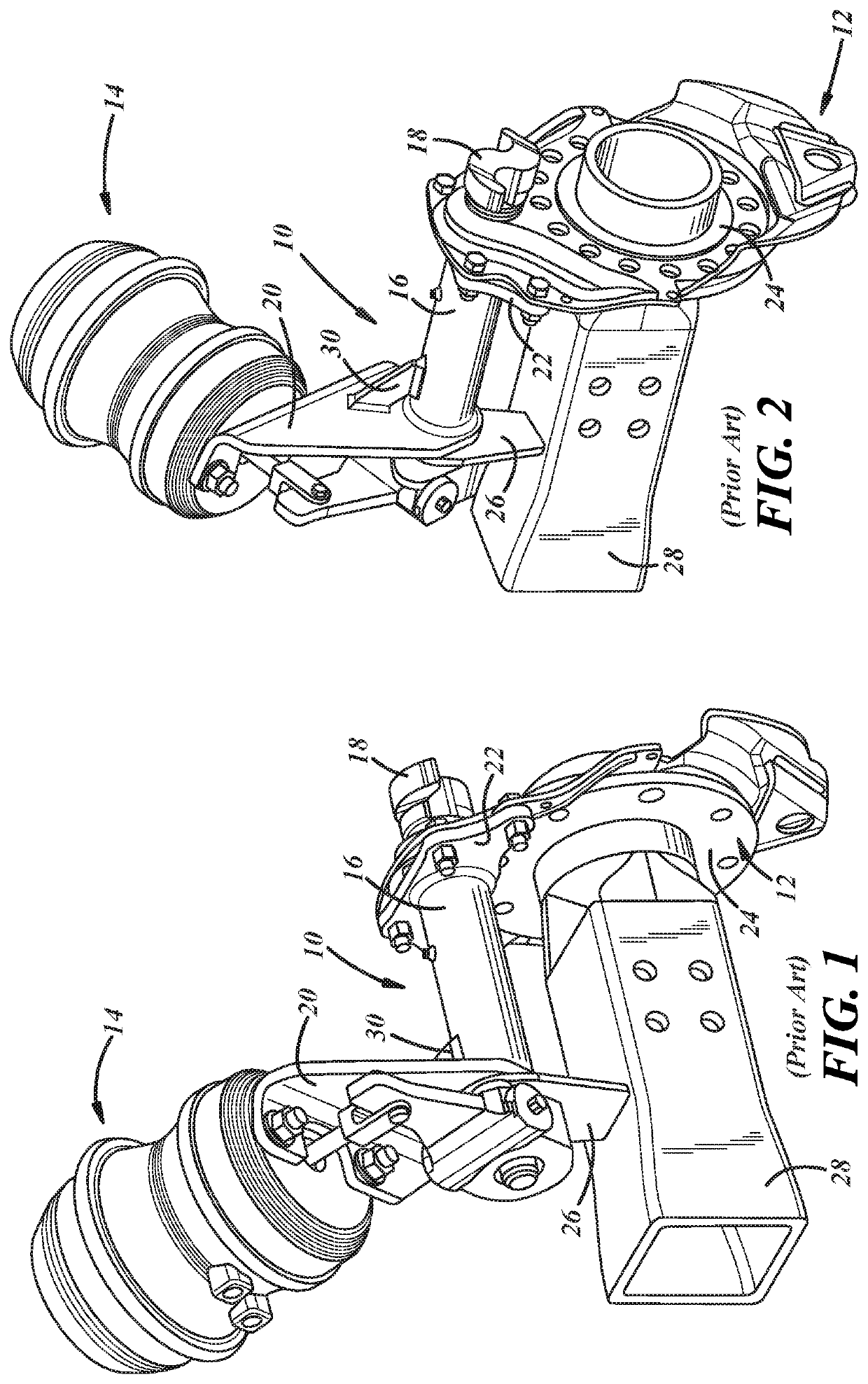
Support 26 adds weight to the vehicle, requires welding to the axle 28 and is generally difficult and costly to assemble.
The welded joints between the tube 16, mounting arm 20 and mounting flange 22 are subject to failure and can result in misalignment of components.
Assembly 10 is also relatively heavy and costly to manufacture—requiring relatively costly tooling.
Further, traditional manufacturing methods for assembly 10 limit flexibility in accommodating different application requirements including loads, mounting hole patterns, available space, varying camshaft lengths and varying brake actuator positions as well as addressing noise and vibration from natural frequencies of the assembly 10.
Traditional manufacturing methods for assembly 10 also make it difficult to establish a desired torsional stiffness (particularly among bracket assemblies of different lengths) thereby requiring slack adjusters between the actuator 14 and camshaft to accommodate large ranges of deflection and making it difficult to set a proper running clearance between the brake shoes and brake drum.

Method used


Image

  • Unitary bracket for mounting a brake assembly and brake actuator
  • Unitary bracket for mounting a brake assembly and brake actuator
  • Unitary bracket for mounting a brake assembly and brake actuator

Examples


Embodiment Construction

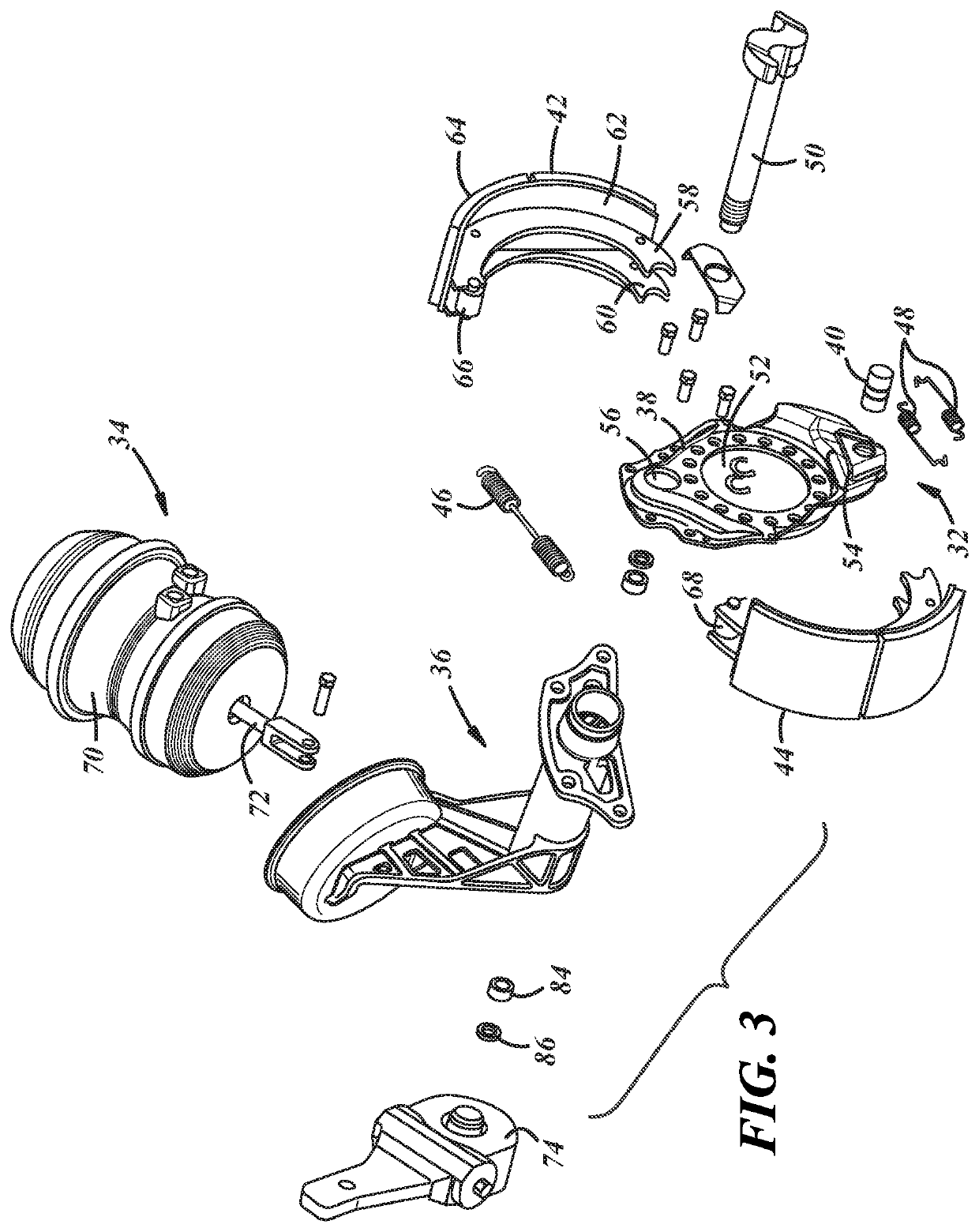
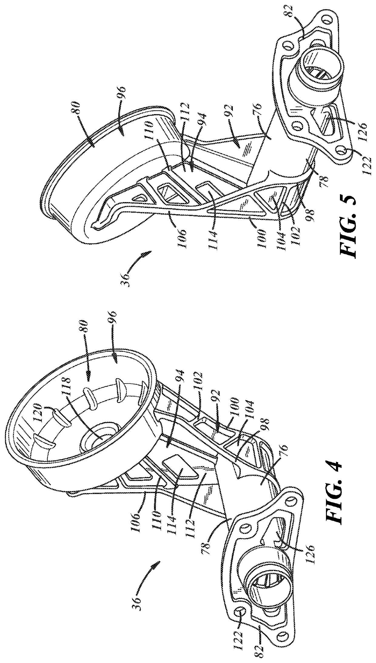
[0021]Referring now to the drawings wherein like reference numerals are used to identify identical components in the various views, FIG. 3 illustrates a brake 32, a brake actuating means 34 and a bracket 36 for mounting the brake 32 and brake actuating means 34 in accordance with one embodiment of the present invention.

[0022]Brake 32 is provided to halt rotation of one or more vehicle wheels. Brake 32 is particularly adapted for use in heavy vehicles. It should be understood, however, that brake 32 may be used on a wide variety of vehicles and in non-vehicular applications. Brake 32 is configured to act against an annular brake drum (not shown) that rotates with the vehicle wheel or wheels at one end of an axle (not shown). Brake 32 may include a brake spider 38, an anchor pin 40, brake shoes 42, 44, return and retaining springs 46, 48, and a camshaft 50.

[0023]Spider 38 is provided to mount the various components of brake 32. Spider 38 defines a central aperture 52 through which the...


PUM


Abstract

A bracket for a brake assembly and a brake actuator includes a unitary body including a tube configured to receive a camshaft of the brake assembly and an actuator mounting arm disposed proximate a first end of the tube and configured to receive the brake actuator. In some embodiments, the tube includes one or more helical ribs formed on a radially inner surface. The bracket further includes either a brake spider or a brake spider mounting flange disposed proximate a second end of the tube. In either embodiment, material may be omitted in various locations to reduce the weight of the bracket. The bracket may be formed through an additive manufacturing process and in a manner that achieve at least one of a predetermined torsional stiffness and attenuation of a predetermined natural frequency.

Description

BACKGROUND OF THE INVENTIONa. Field of the Invention[0001]This invention relates to vehicle brakes. In particular, the invention relates to a bracket for mounting a brake assembly and a brake actuator that provides improved performance while reducing the cost of manufacture and vehicle assembly and also allowing improved control of torsional stiffness and noise attenuation.b. Background Art[0002]In a conventional drum brake, a brake drum rotates with a wheel or wheels proximate to one end of an axle. The drum defines a radially inner braking surface. A brake spider is disposed about the axle and a pair of brake shoes are pivotally mounted at one end to the brake spider. The opposite end of each brake shoe is engaged by an actuating member such as a cam to move the brake shoes between positions of engagement and disengagement with the braking surface of the brake drum. The cam is driven by a brake actuator acting on one end of a camshaft supporting the cam.[0003]Referring to FIGS. 1-...

Claims


Application Information

Patent Timeline
Patent Type & Authority Patents(United States)
IPC IPC(8): F16D51/22F16D51/20F16D65/09F16D65/22B33Y10/00B33Y50/00B33Y80/00F16D125/30F16D51/00F16D121/08
CPCF16D51/20B33Y10/00B33Y50/00B33Y80/00F16D65/09F16D65/22F16D2051/003F16D2121/08F16D2125/30F16D2250/00B60T17/088F16D65/0056
Inventor BANKS, DANIEL E.
Owner BENDIX COMML VEHICLE SYST LLC
Learn More