Method and network control device for optimizing performance of a multi-span optical fiber network

a multi-span, optical fiber technology, applied in the direction of electromagnetic network arrangement, transmission monitoring, optical transmission with multiple stages, etc., can solve the problems of reducing the available transmission rate, reducing the optimum launch power, and high power launched into the fiber causing nonlinear distortion

Active Publication Date: 2022-11-01
ADVA OPTICAL NETWORKING SP ZOO
View PDF5 Cites 0 Cited by
  • Summary
  • Abstract
  • Description
  • Claims
  • Application Information

AI Technical Summary

Benefits of technology

[0012]Further, for each span, the computed optimum launch power can be used to calculate a maximum generalized optical signal-to-noise ratio of the span. Further, the calculated maximum generalized optical signal-to-noise ratios of all spans can then be used to optimize the performance of the multi-span optical fiber network. The maximization of the generalized optical signal-to-noise ratio results in the optimization of signal primary measurable characteristics, for example the maximization of the signal-to-noise ratio and the signal parameter Q, as well as the minimization of the bit-error-rate.
[0029]Therein, in the multi-span optical fiber network pairs of nodes of the network can be associated with distinct bands of optical channels used for communication between the pairs of nodes, wherein the calculation means can be configured to separately calculate a maximum generalized optical signal-to-noise ratio for each channel based on the computed optimum launch powers of all spans of the respective channel, wherein the network interface device further comprises a second determining means which is configured to determine a worst generalized optical signal-to-noise ratio from the calculated maximum generalized optical signal-to-noise ratios, and wherein the optimizing means is configured to use the worst generalized optical signal-to-noise ratio to optimize the performance of the multi-span optical fiber network. Thus, the effectiveness of optimizing the performance of the multi-span optical fiber network can be further improved by removing the assumption that the central channel is the worst performing channel, which may not be the worst performing channel in the field, wherein at the same time the computational effort required to optimize the multi-span optical fiber network can be further reduced.

Problems solved by technology

Low power launched into the fiber yields a low optical signal-to-noise ratio (OSNR), which reduces the available transmission rate.
High power launched into the fiber produces nonlinear distortions.
However, this over-simplification leads to an error in the estimation of the optimum launch power, in particular as there are optical amplifiers known with independent gain and output power controls.

Method used


Image

  • Method and network control device for optimizing performance of a multi-span optical fiber network
  • Method and network control device for optimizing performance of a multi-span optical fiber network
  • Method and network control device for optimizing performance of a multi-span optical fiber network

Examples


Embodiment Construction

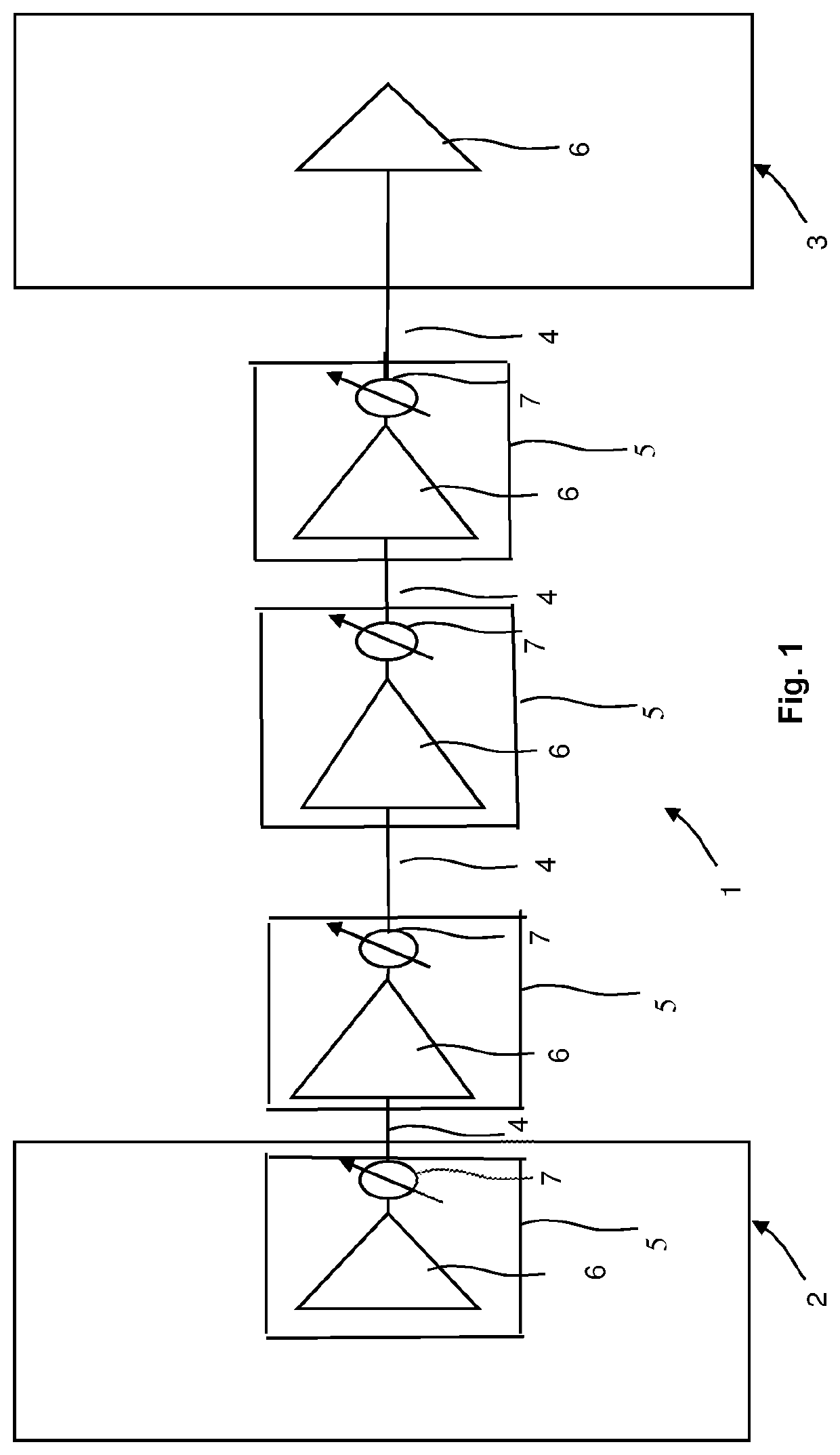
[0041]FIG. 1 illustrates an example section 1 of an optical fiber network. The network is a wavelength-division multiplexing (WDM) Network.

[0042]As shown in FIG. 1, an ingress WDM node 2 is connected to an egress WDM node 3 via spans 4 of optical fiber. The spans 4 of optical fiber are coupled via optical amplifiers 5. An amplifier 5 in the ingress node 2 is optically coupled to the first span 4 of optical fiber. An amplifier 5 in the egress node 3 is optically coupled to the final span 4 of optical fiber.

[0043]The optical amplifiers 5 shown in FIG. 1 are optical amplifiers with independent gain and output power controls and amplifier noise figure dependence on amplifier gain. In this regard, FIG. 1 also shows variable-gain amplifier 6 and corresponding variable optical attenuators (VOA) 7, wherein the output power is respectively controlled using the respective variable optical attenuator 7. Here, the actual amplifier 6 and the variable optical attenuator 7 are respectively shown b...


PUM


Abstract

The present invention relates to a method for optimizing performance of a multi-span optical fiber network. Each span has an associated optical transmission fiber connected to an associated optical amplifier. Gain and output power of the associated optical amplifier are respectively controlled independently. An amplifier noise figure respectively depends on the gain of the associated optical amplifier, with each associated optical amplifier further connected to launch optical signals into a remainder of a corresponding optical transmission line. The method includes the steps of for each span, computing the amplifier noise figure and a non-linear noise generated in the span based on information about the span and using the computed amplifier noise figure and the computed non-linear noise to compute an optimum launch power, and optimizing performance of the multi-span optical fiber network based on the computed optimum launch powers of all spans.

Description

BACKGROUND OF THE INVENTIONField of the Invention[0001]The present application relates to optical communication systems and, in particular, to a method for optimizing performance of a multi-span optical fiber network that takes into account non-linear effects.Description of Related Art[0002]In an optical fiber transmission line of an optical communication system, an amplifier couples sequentially related optical transmission fiber spans. The amplifiers produce adequate optical launch powers to compensate for power losses to optical signals in the immediately preceding fiber span and other elements.[0003]Further, network operators have a strong interest in making most efficient use of their investments in the network infrastructure, and therefore, a strong interest in achieving the highest transmission capacity through the fiber optical transmission lines in the network. Therein, for most fiber optical transmission lines impairments determining the total capacity of the fiber within ...

Claims


Application Information

Patent Timeline
Patent Type & Authority Patents(United States)
IPC IPC(8): H04B10/00H04B10/69H04B17/336H04B10/077H04B10/293H04B10/297H04B10/291
CPCH04B10/697H04B10/0777H04B10/2935H04B10/2972H04B17/336H04B10/2916H04B10/27H04B10/2939H04B2210/003
Inventor TIBULEAC, SORINSEARCY, STEVENBURTSEV, SERGEY
Owner ADVA OPTICAL NETWORKING SP ZOO
Why Eureka
Try Eureka