Transparent desiccant for organic EL, and method for using same

a desiccant and organic el technology, applied in the field of desiccant for organic electroluminescent devices, to achieve the effect of suppressing the degradation of organic el elements, high transparency, and small shrinkage of pixels

Active Publication Date: 2022-11-08
SHIN ETSU CHEM CO LTD
View PDF42 Cites 0 Cited by
  • Summary
  • Abstract
  • Description
  • Claims
  • Application Information

AI Technical Summary

Benefits of technology

[0017]The transparent desiccant for an organic EL device of the invention is highly transparent, has a small growth in pixel shrinkage under high temperature and high humidity, and can suppress organic EL element degradation (dark spot formation). Moreover, because the transparent desiccant of the invention is highly transparent, it is suitable for top-emitting EL devices which transmit the light emitted by an organic EL element through the top side of the device.
[0018]Also, the inventive method of using the transparent desiccant for an organic EL device disposes the desiccant within an organic EL panel. In cases where it is necessary to thinly form the desiccant, it is possible to form the organopolysiloxane composition into a thin film having an excellent degassing ability in a curing step following application of the composition.
[0019]In addition, with regard to the transparent desiccant and method of use of the invention, the transparent desiccant need not be in contact with the organic EL element. The low-molecular-weight siloxane within the desiccant diffuses and accumulates within the organic EL panel, insulating the vicinity of small particles that have become present during formation of the organic EL element and making it possible to achieve the effect of suppressing electrical shorting between the cathode and the anode by the particles.

Problems solved by technology

However, a drawback is that the elements are damaged by the ingress of even a trace amount of moisture into the panel (generating dark spots).
However, an electrical short-circuit (shorting) between the cathode and the anode sometimes arises due to the presence of a small particle.
When shorting arises, the elements around the particle causing the shorting must be separated with a laser or the like, which gives rise to problems such as partial loss of the emitted light and an increased number of fabrication steps.
However, with a desiccant-containing silicone rubber, not only is it difficult to obtain light transmittance, when the silicone rubber is thinly formed, additional challenges include the presence of bubbles therein.
In this method, there is a gradual loss of light transmittance as moisture absorption proceeds due to reaction of the metal alkoxide with moisture, and so maintaining the initial light transmittance is difficult.
Also, in this method, a short circuit-suppressing effect is difficult to obtain.

Method used


Image

  • Transparent desiccant for organic EL, and method for using same
  • Transparent desiccant for organic EL, and method for using same

Examples


preparation example 1

[Preparation of Organopolysiloxane Composition 1]

[0065]Thirty parts of a dimethylpolysiloxane capped at both ends with Me2ViSiO1 / 2 units (weight-average molecular weight, 1,000) and 70 parts of a dimethylpolysiloxane capped at both ends with Me2ViSiO1 / 2 units (weight-average molecular weight, 5,000) were used as Component (A), and organohydrogenpolysiloxanes of the following average formula

H1.29Me0.72SiO1.98 / 2

wherein the number of moles of silicon-bonded hydrogen atoms per unit weight Y (mol / g) relative to the number of moles of silicon-bonded vinyl groups per unit weight X (mol / g) in component (A) satisfies formulas (1) to (3) below

Y−X=0.06 mol / g  (1)

Y−X=0.6 mol / g  (2)

Y−X=1.3 mol / g  (3)

were each prepared as component (B).

[0066]In addition, 0.1 part of a 1,1-divinyltetramethyldisiloxane complex solution of chloroplatinic acid (1 wt %, based on elemental platinum) was used as component (C) and 0.03 part of 1-ethynyl-1-cyclohexanol was used as the hydrosilylation reaction regulator, ...

preparation example 2

[Preparation of Organopolysiloxane Composition 2]

[0067]In the organopolysiloxane serving as component (A), components (A-1) and (A-2) below:

(A-1) a resinous organopolysiloxane having at least two alkenyl groups per molecule, and

(A-2) a linear organopolysiloxane having at least two alkenyl groups per molecule were each prepared such that the sum of (A-1) and (A-2) was 100 wt % and to the following ratios (i) and (ii).

[0068](i) (A-1):(A-2)=1:99

[0069](ii) (A-1):(A-2)=50:50

[0070]Specifically, 49.0 parts of a resinous organopolysiloxane consisting of 6.8 mol % of Me2ViSiO1 / 2 units, 39.8 mol % of Me3SiO1 / 2 units and 53.4 mol % of SiO4 / 2 units (weight-average molecular weight=6,000: Composition a) and 1.0 part of a resinous organopolysiloxane consisting of 50 mol % of Me2ViSiO1 / 2 units and 50 mol % of MeSiO3 / 2 units (weight-average molecular weight=5.000: Composition b) were used as component (A-1), and 15 parts of a dimethylpolysiloxane capped at both ends with Me2ViSiO1 / 2 units (weight-a...

example 1

[0076]The organopolysiloxane composition was prepared as described in Preparation Example 1, with preparation being carried out such that the number of moles of silicon-bonded hydrogen atoms per unit weight Y (mol / g) in the organohydrogenpolysiloxane relative to the number of moles of silicon-bonded vinyl groups per unit weight X (mol / g) in component (A) satisfies the following formula

Y−X=0.06 mol / g.

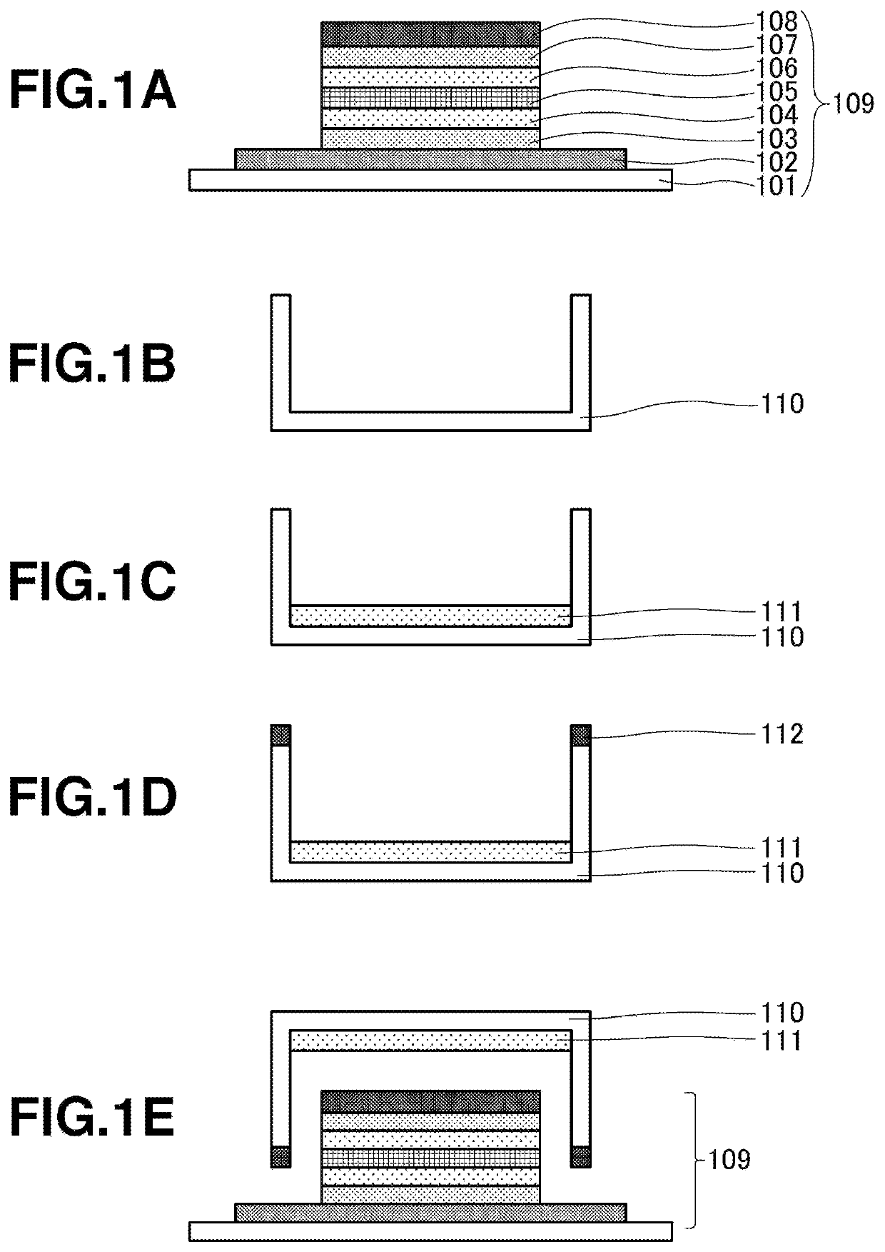
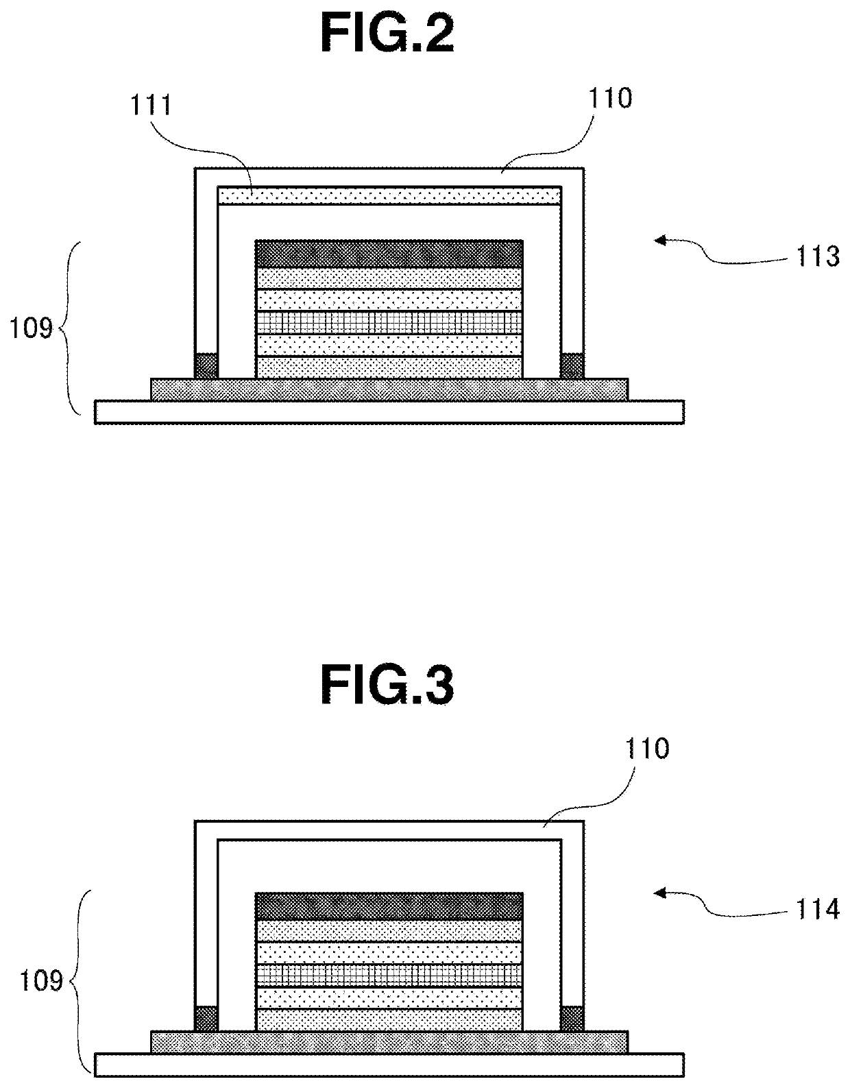
[0077]The resulting organopolysiloxane composition was disposed within the organic EL panel by the procedure described in the above organic EL panel fabrication process, thereby giving the organic EL panel (113) shown in FIG. 2 having a transparent desiccant attached therein. The amount of organopolysiloxane composition added by dripping within the organic EL panel was set to 0.043 g (an amount corresponding to a thickness of 30 μm).


PUM

PropertyMeasurementUnit
thicknessaaaaaaaaaa
temperatureaaaaaaaaaa

Abstract

A transparent desiccant for organic EL and methods for using the transparent desiccant are described, which is a cured product of an organopolysiloxane composition that contains (A) an alkenyl-group-containing organopolysiloxane including a linear organopolysiloxane having at least two alkenyl groups per molecule, (B) chemical formula (I):HaRbSiO(4-a-b) / 2  (I)(where R is a C1-10 monovalent hydrocarbon group, a is 0.001-1.0, and b is 0.7-2.1), and (C) a hydrosilylation catalyst. The number of mol Y of silicon-atom-bonded hydrogen atoms (mol) in component (B) satisfies the formula 0.002 (mol)≤(Y-X)≤0.8 (mol) relative to the number of mol X of silicon-atom-bonded alkenyl groups (mol) in component (A). The transparent desiccant for an organic EL is highly transparent, capable of top emission, has low shrinkage growth, suppresses loss of an element light-emitting portion, suppresses the short-circuit phenomenon, and has exceptional defoaming properties in the material curing process.

Description

TECHNICAL FIELD[0001]The present invention relates to a desiccant for an organic electroluminescent (EL) device, and a method of using the desiccant.BACKGROUND ART[0002]In organic electroluminescent (abbreviated below as “organic EL”) panels, because the panel elements are “self-emissive,” i.e., they emit light themselves, the panel does not require a separate light source such as the backlight in a liquid-crystal panel and thus has a low power consumption. Other characteristics of such panels include the ease of achieving a lower profile and a lighter weight. In addition, they reportedly have a higher picture quality than liquid-crystal panels. However, a drawback is that the elements are damaged by the ingress of even a trace amount of moisture into the panel (generating dark spots).[0003]Because organic EL panels must be constructed so as to prevent moisture ingress to a high degree, a structure that hermetically seals the organic EL elements with, for example, a light-transmissi...

Claims


Application Information

Patent Timeline
Patent Type & Authority Patents(United States)
IPC IPC(8): H01L51/52B01J20/26H01L51/56B01J20/28
CPCH01L51/5259B01J20/26B01J20/262B01J20/28033H01L51/5246H01L51/56H01L2251/558B01D53/28B01D53/26C08G77/50H05B33/04H10K50/846C08G77/20H10K50/8426H10K71/00H10K2102/351
Inventor OHWADA, HIROTOIGARASHI, MINORUNAKAMURA, TSUTOMU
Owner SHIN ETSU CHEM CO LTD
Why Eureka
Try Eureka