Process for the production of synthesis gas

a technology of synthesis gas and process, applied in the field of process for the production of synthesis gas, can solve the problems of inability to adapt effectively, inability to operate conveniently apart from the design capacity, and inability to meet the needs of the user,

Inactive Publication Date: 2001-07-05
BADANO MARCO
View PDF0 Cites 40 Cited by
  • Summary
  • Abstract
  • Description
  • Claims
  • Application Information

AI Technical Summary

Benefits of technology

[0024] Advantageously, thanks to the step wherein a second flow of hydrocarbons is reacted in an autothermal reforming section, it is possible to face easily and effectively even substantial capacity variations of the plant implementing the process according to the invention.
[0026] In this way, it is possible to apportion the desired total production of synthesis gas in the two reforming stages, whose capacity may be therefore varied from time to time and independently according to the specific demand, without negatively affecting the remaining process.
[0030] A further advantage, resulting from the process according to the invention, is given by the fact that, having the possibility of feeding separate flows of hydrocarbons to reforming stages independent from each other, it is advantageously possible to use for the production of synthesis gas hydrocarbons of different nature in the different reforming stages, thus adapting the process to the existing natural resources and to whichever requirement may arise.
[0033] This feature is particularly advantageous for a subsequent urea synthesis, since it allows the achievement--effectively and cheaply--of a CO.sub.2 / NH.sub.3 stoichiometric ratio and therefore to increase the conversion yield of fed carbon into CO.sub.2 and thus urea.
[0047] Thanks to the aforesaid method of retrofitting it is possible easily to increase remarkably the production capacity of an existing plant for the production of synthesis gas, with low operating and investment costs and with low energy consumption.

Problems solved by technology

First of all the fact of being little flexible and not able to adapt themselves effectively to variations in the operating conditions, in particular when significant increases in the amount of synthesis gas to be produced are required.
In fact, the primary and secondary reforming sections, responsible for the conversion of hydrocarbons, are not able to operate conveniently apart from the design capacity.
Therefore, in order to adapt the synthesis gas producing plants which operate according to the above described processes to the capacity increases required more and more in this field, dramatic interventions of retrofitting and, last but not least, the replacement of the reforming sections themselves with sections having increased capacity are necessary, with very high investment costs.
Because of these drawbacks, the implementation of synthesis gas producing processes according to the prior art requires today high investments and energy consumption, such to penalise remarkably the costs of base chemicals such as hydrogen and carbon monoxide, despite the ever increasing demand for these products.

Method used


Image

  • Process for the production of synthesis gas

Examples


example

[0107] In the following example, the advantages resulting from the method of retrofitting according to the present invention are displayed.

[0108] In particular, the energy consumption relative to a capacity increase equal to 50% of an existing plant for the production of synthesis gas for obtaining ammonia is discussed.

[0109] The results of the instant example have been obtained by means of commercially available calculation algorithms.

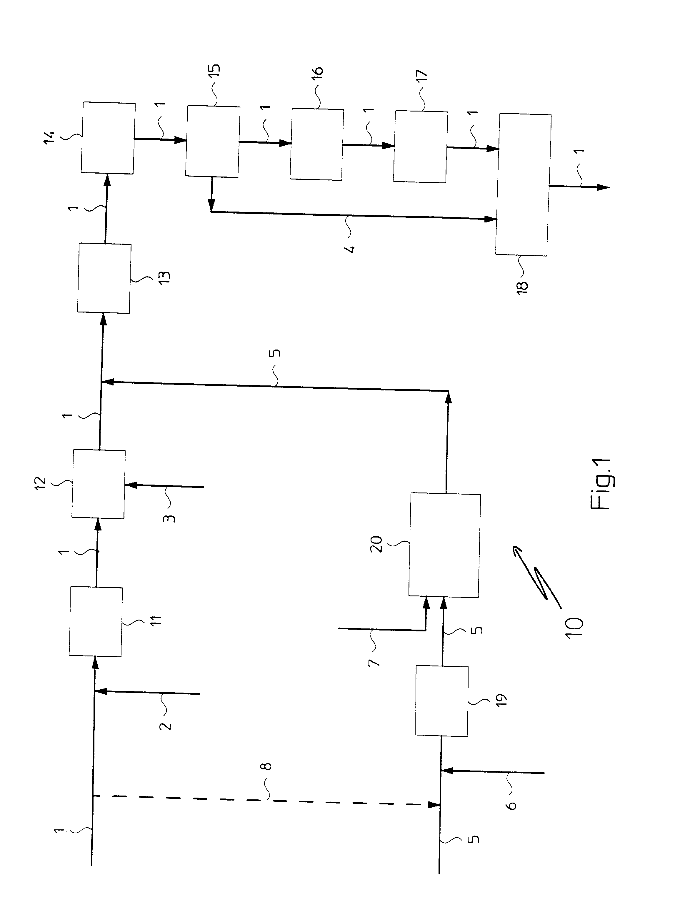
[0110] The existing plant is of the type shown and described with reference to FIG. 1, blocks 11-17, and was designed to operated at an average production capacity of 1000 MTD of ammonia. The overall energy consumption is normally of 8300 kcal / MT of ammonia.

[0111] Natural gas is used as a source of hydrocarbons and the gas flow comprising oxygen fed to the secondary reforming section consists of air.

[0112] The primary and secondary reforming sections of the existing plant were not designed for facing a capacity increase equal to 50% but on the contrar...


PUM

PropertyMeasurementUnit
temperatureaaaaaaaaaa
flexibleaaaaaaaaaa
energy consumptionaaaaaaaaaa

Abstract

A process for the production of synthesis gas for obtaining compounds such as ammonia or methanol, in which hydrocarbons and steam are reacted first in a primary reforming section (11) and then-together with oxygen-in a secondary reforming section (12), thus obtaining CO, CO2, H2 and possibly N2 which are then fed to a carbon monoxide conversion section (13, 14), is distinguished by the fact of reacting hydrocarbons, steam and oxygen in an autothermal reforming section (20) provided in parallel with respect to other reforming sections (11, 12), and feeding the so produced CO, CO2, H2 and possibly N2 to the carbon monoxide conversion section (13, 14).

Description

FIELD OF APPLICATION[0001] The present invention relates to a process for the production of synthesis gas for obtaining compounds such as ammonia and methanol.[0002] More specifically, the invention relates to a process for the production of synthesis gas comprising the steps of:[0003] feeding a first flow comprising hydrocarbons and a first gas flow comprising steam to a primary reforming section;[0004] feeding a first gas flow comprising oxygen and possibly nitrogen to a secondary reforming section;[0005] reacting the hydrocarbons and steam first in the primary reforming section and then--together with oxygen--in the secondary reforming section, obtaining a first gas phase comprising CO, CO.sub.2, H.sub.2 and possibly N.sub.2;[0006] feeding the first gas phase comprising CO, CO.sub.2, H.sub.2 and possibly N.sub.2 to a carbon monoxide conversion section.[0007] Throughout this specification and the appended claims, the term: "hydrocarbons" is used to indicate generically a raw mater...

Claims


Application Information

Patent Timeline
Patent Type & Authority Applications(United States)
IPC IPC(8): C01B3/02C01B3/38C01B3/48
CPCC01B3/025C01B3/382C01B3/48C01B2203/0233C01B2203/0244C01B2203/0288C01B2203/0475C01B2203/06C01B2203/061C01B2203/068C01B2203/0844C01B2203/1011C01B2203/1241C01B2203/1247C01B2203/141C01B2203/142C01B2203/143C01B2203/146C01B2203/82
Inventor BADANO, MARCO
Owner BADANO MARCO
Why Eureka
Try Eureka