Linear aperture deposition apparatus and coating process

a technology of deposition apparatus and coating process, which is applied in the direction of instruments, optical elements, transportation and packaging, etc., can solve the problems of high capital cost of vacuum coating equipment, limited economic production of these coatings, and inability to meet the requirements of large-scale commercial applications, etc., to achieve the effect of reducing the length of the chimney and increasing the temperature of the chimney

Inactive Publication Date: 2001-08-09
JDS UNIPHASE CORP
View PDF0 Cites 58 Cited by
  • Summary
  • Abstract
  • Description
  • Claims
  • Application Information

AI Technical Summary

Benefits of technology

[0032] Another object of the present invention is to provide a sublimation and evaporative coating apparatus and process that satisfies the need for high and stable deposition rates, thickness control, high coating quality, and efficient use of the source materials.
[0118] When using the various embodiments of the invention to coat dielectric substrates, such as polyester film or glass, it is necessary to remove static charge buildup on the substrate to deposit high-quality coatings such as a zinc sulfide coating. Without treating dielectric substrates in this manner, the coatings are of lower quality and have a mottled appearance, suggesting it is structurally or chemically inhomogeneous. These generally undesirable characteristics are more prominent as the coating thickness is decreased, corresponding to lower deposition rate. Not wishing to be bound by theory, we believe the film quality is related to the nucleation rate, in that nucleation is suppressed by the residual static charge. A static charge on the substrate would repel one of the ionized species (e.g., Zn when the static charge is positive). Nucleation and growth require that either both ions, or ZnS molecules, are present at the gas-surface interface. The degradation in film quality at the lower deposition rates suggests that either the ionized species are rate limiting or the excess ions become incorporated in the film growing from ZnS molecules, disrupting the film's structure. The static charge is easily removed with a glow discharge on plastic or glass substrate. Metallic or metal-coated substrates, when they are sufficiently conductive, do not accumulate a static charge, obviating the need for a glow discharge treatment.

Problems solved by technology

The economical production of these coatings is frequently limited by the thickness uniformity necessary for the product, the number of layers, and the deposition rate of the coating materials.
The high capital cost of vacuum coating equipment necessitates a high throughput of coated area for large-scale commercial applications.
The manufacturing cost of the product is ultimately limited by the specific performance requirements that limit the maximum deposition rate.
However, magnetron sputtering equipment is relatively expensive, is limited to materials that can be readily formed into solid targets, and has deposition rates that are generally inferior to those of thermal evaporation technologies, especially for metal compounds that are useful as optical coating materials.
It is generally believed that such spatter is generated by the non-uniform heating of a granular or otherwise non-homogeneous source material whereby locally high pressures cause the ejection of the most friable portions of the source material.
Spatter is severe in source materials with a low thermal conductivity and having retained moisture, air or other high vapor pressure components, and increases with the heating rate due to increased temperature differentials.
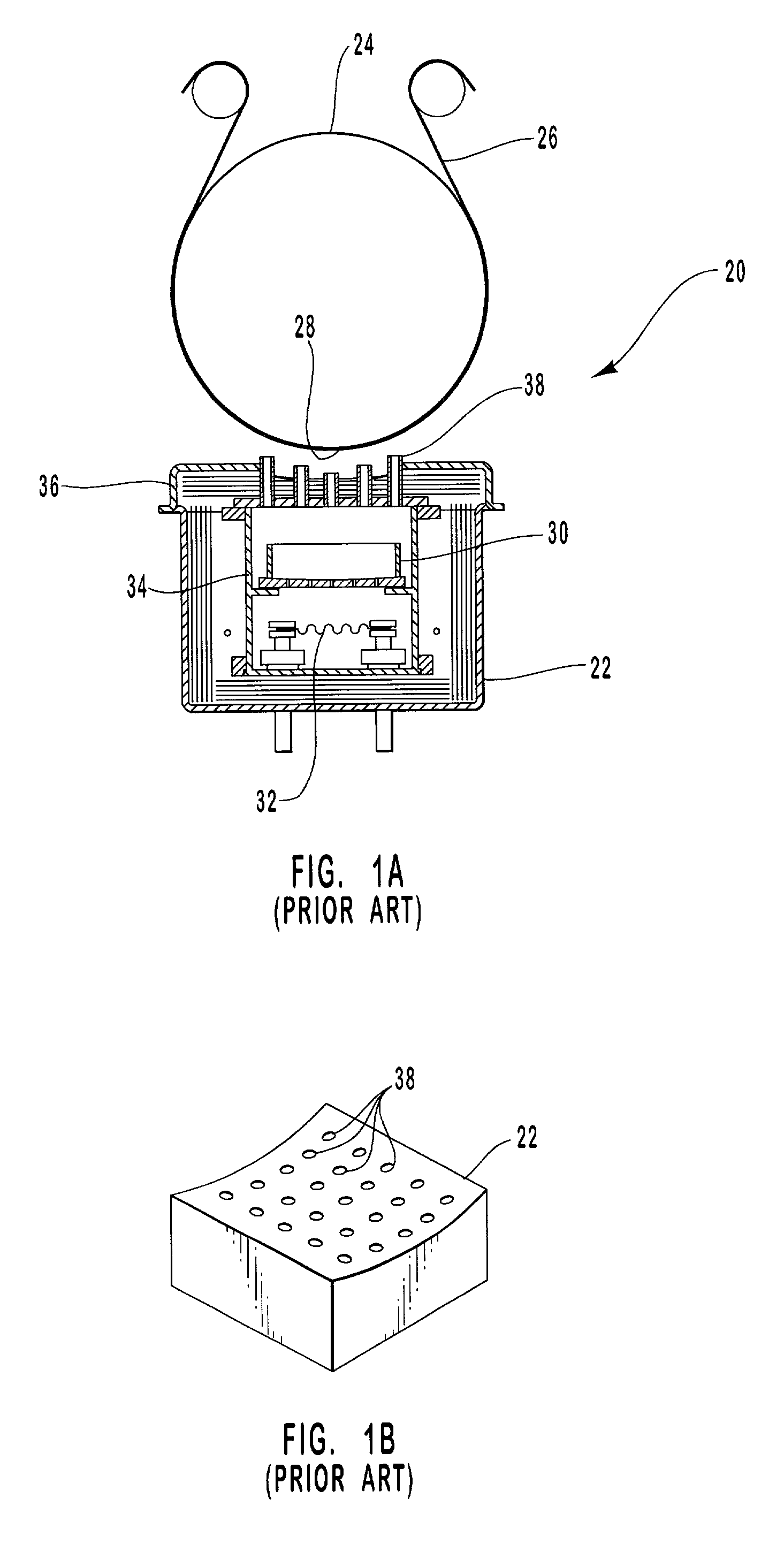
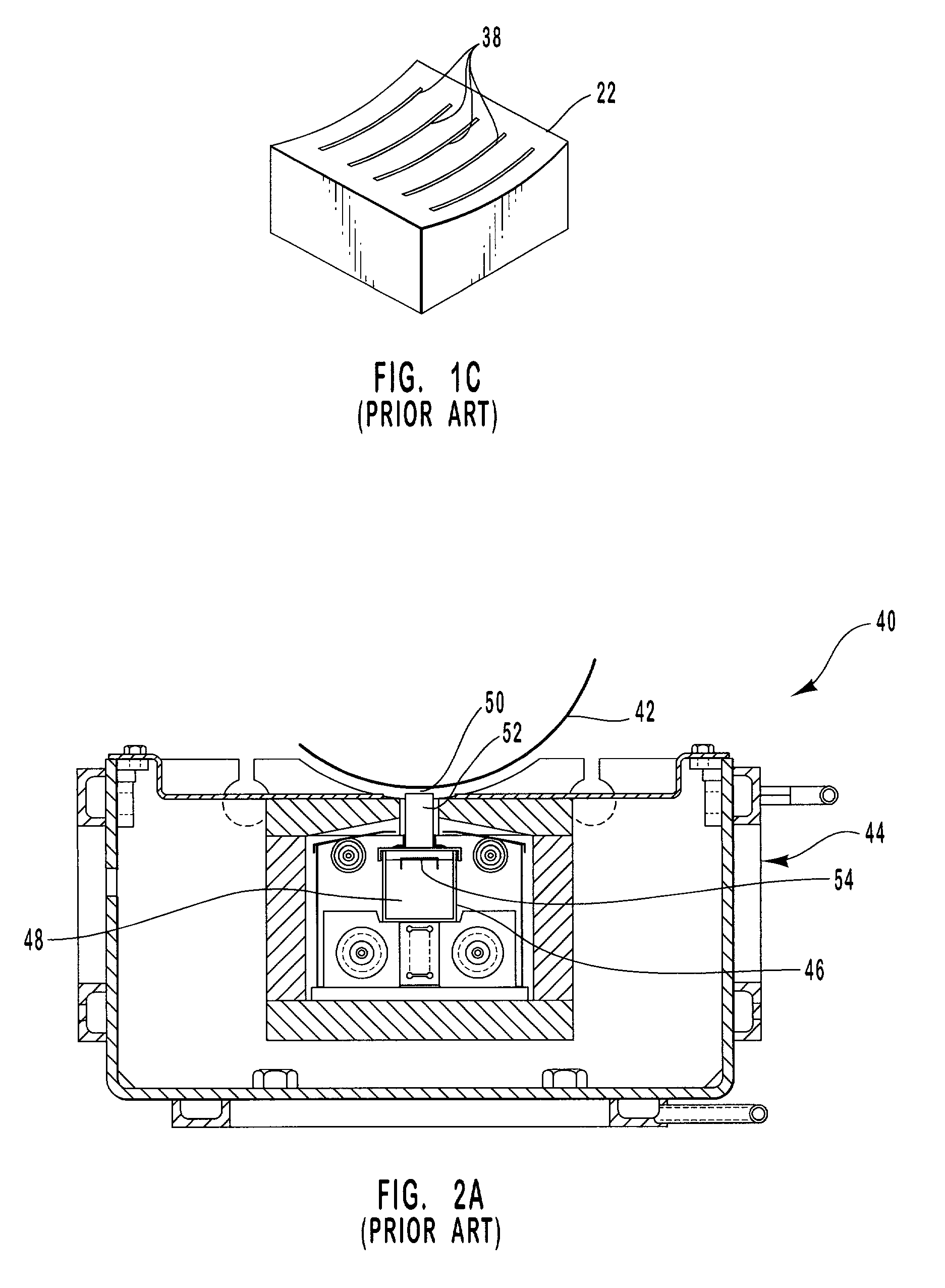
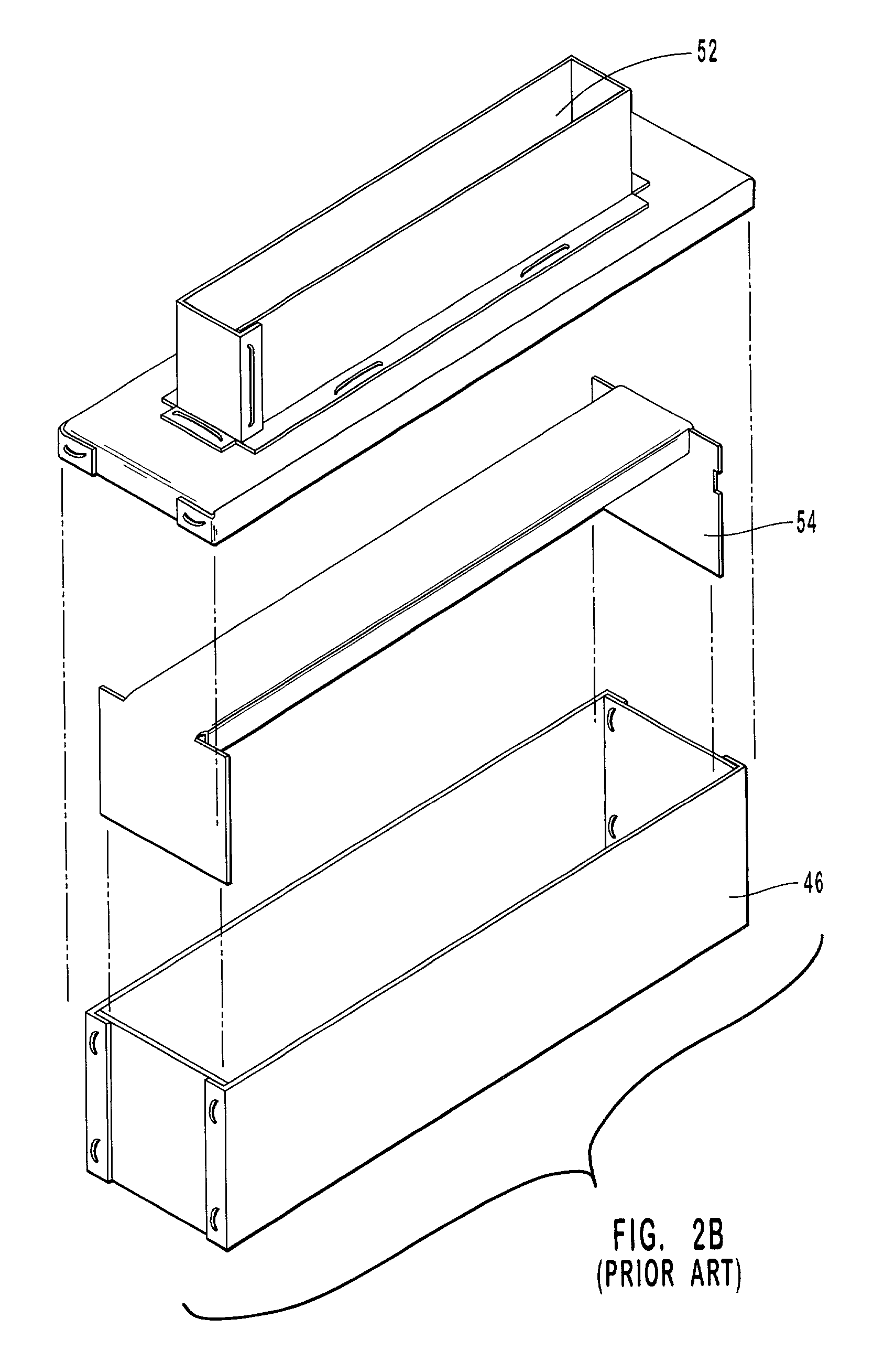
Although a tubular Knudsen cell is easy to fabricate, it can be difficult to uniformly fill with solid source material, especially when the slit is relatively narrow with respect to the width of the source material particles.
Prior art methods of depositing dielectric materials from either a series of electron beam point sources or linear crucibles have numerous limitations, especially for the economical production of optical interference coatings.
Both the chamber and masking fixtures must be cleaned periodically, resulting in lower utilization of the capital equipment capacity and higher material costs.
Attempts to increase deposition rate by increasing source power input, such as electron beam current, result in either an unstable melt pool, or can further decrease the coating uniformity or increase the rate of particulate ejection, i.e., spatter, from solid or subliming and liquid materials.
Either coating uniformity or surface quality considerations always limit the deposition rate.
The development of a linear source for the evaporation of higher refractive index materials has been a particularly elusive problem.
While some successes have been obtained in depositing silicon monoxide and materials that sublime at a temperature less than about 900.degree. C., this limits the available refractive index to a range from about 1.6 to about 1.9.
Furthermore, prior art methods of coating plastic films are frequently limited to specific substrates depending on the heating load of the source and the substrate's heat deformation temperature.
This limits the choice of coating materials that can be evaporated and the maximum coating thickness.
Continuous vacuum coating of plastic substrates requires numerous compromises to be made in product cost, composition, performance or quality due to deposition source technology.
Its relatively low sublimation temperature range, from about 1000.degree. C. to about 1900.degree. C., would suggest that it is an ideal material for plastic web coating, but it has two inherent material problems.
Sub-stoichiometric ZnS has undesirable optical absorption.
Also the uncontrolled dissociation results in residual sulfur compounds on vacuum chamber components, most notably in the vacuum oil, and an undesirable odor.
Further, chemical reactions of the excess sulfur may accelerate the deterioration of various vacuum components.

Method used


Image

  • Linear aperture deposition apparatus and coating process
  • Linear aperture deposition apparatus and coating process
  • Linear aperture deposition apparatus and coating process

Examples


Embodiment Construction

[0120] In this example, a floating baffle and flow restricting baffle were utilized as shown in the embodiment of FIG. 3C. The crucible was formed from a rectangular box having dimensions 2.times.2.times.9.5 in. The dimensions of the other source components were:

1 L 9.5 in. H 3.5 in. W1 0.625 in. Crucible width, W2 2 in. Distance from chimney 0.437 in. to substrate, D Drum diameter, D' 11.8 in. (30 cm) L / D ratio 21.7 H / W1 ratio 5.6 W2 / W1 ratio 3.2 D / D' 0.037

[0121] The flow restricting baffle contained five rows of 3-mm holes to prevent ZnS particulate from being ejected from the source material. The substrate was polyester film having a thickness of 0.002 in. The polyester had been aluminized to facilitate coating thickness measurements. There was no shutter between the source and the substrate, nor was there any masking.

[0122] Base pressure was 5.times.10.sup.-5 Torr. The stability and source uniformity were evaluated at two conditions, denoted "A" and "B". In condition A, 1.4 kW o...


PUM

PropertyMeasurementUnit
thicknessaaaaaaaaaa
thicknessaaaaaaaaaa
thicknessaaaaaaaaaa

Abstract

A linear aperture deposition apparatus and process are provided for coating substrates with sublimed or evaporated coating materials. The apparatus and process are particularly suited for producing flexible films having an optical interference coating with a very high surface thickness uniformity and which is substantially free of defects from particulate ejection of a source material. The apparatus includes a source box containing a source material, a heating element to sublime or evaporate the source material, and a chimney to direct the source material vapor from the source box to a substrate. A flow restricting baffle having a plurality of holes is positioned between the source material and the substrate to confine and direct the vapor flow, and an optional floating baffle is positioned on the surface of the source material to further restrict the vapor flow, thereby substantially eliminating source material spatter.

Description

[0001] This application claims the benefit of priority to U.S. Provisional Application Ser. No. 60 / 108,187, filed on Nov. 12, 1998, the disclosure of which is herein incorporated by reference.[0002] 1. Field of the Invention[0003] The present invention relates generally to the field of vacuum deposition processes, and more particularly to a linear aperture deposition apparatus and coating process for coating wide substrate materials.[0004] 2. Relevant Technology[0005] Optical interference coatings are useful for controlling the reflection, transmission and / or absorption of a selected wavelength range of light. These coatings consist of a plurality of alternating layers having a predetermined thickness less than the selected wavelength range. Additionally, the layers have a significant difference in refractive index and are controlled to a predetermined thickness. Suitable materials for optical interference coatings are primarily dielectric materials which have a refractive index ran...

Claims


Application Information

Patent Timeline
Patent Type & Authority Applications(United States)
IPC IPC(8): C23C14/24G02B5/28C23C14/56
CPCC23C14/243C23C14/562Y10T428/31681
Inventor WITZMAN, MATTHEW R.BRADLEY, RICHARD A. JR.LANTMAN, CHRISTOPHER W.COX, ERIC R.
Owner JDS UNIPHASE CORP
Why Eureka
Try Eureka