Closed cycle photocatalytic process for decomposition of hydrogen sulfide to its constituent elements

a photocatalytic process and closed cycle technology, applied in the field of closed cycle photocatalytic process for decomposition of hydrogen sulfide to its constituent elements, can solve the problems of h.sub.2s gas in the refinery

Inactive Publication Date: 2001-10-04
UNIV OF CENT FLORIDA
View PDF0 Cites 12 Cited by
  • Summary
  • Abstract
  • Description
  • Claims
  • Application Information

AI Technical Summary

Benefits of technology

0010] The energy to drive the reaction can either come from the sun or an artificial light source. The decomposition process is photoelectrochemical in nature, in which the photovoltaic effect from semiconductor solid

Problems solved by technology

The problem is what do the refineries do with the H.sub.2S gas, which

Method used


Image

  • Closed cycle photocatalytic process for decomposition of hydrogen sulfide to its constituent elements
  • Closed cycle photocatalytic process for decomposition of hydrogen sulfide to its constituent elements
  • Closed cycle photocatalytic process for decomposition of hydrogen sulfide to its constituent elements

Examples


Embodiment Construction

[0019] Before explaining the disclosed embodiment of the present invention in detail it is to be understood that the invention is not limited in its application to the details of the particular arrangement shown since the invention is capable of other embodiments. Also, the terminology used herein is for the purpose of description and not of limitation.

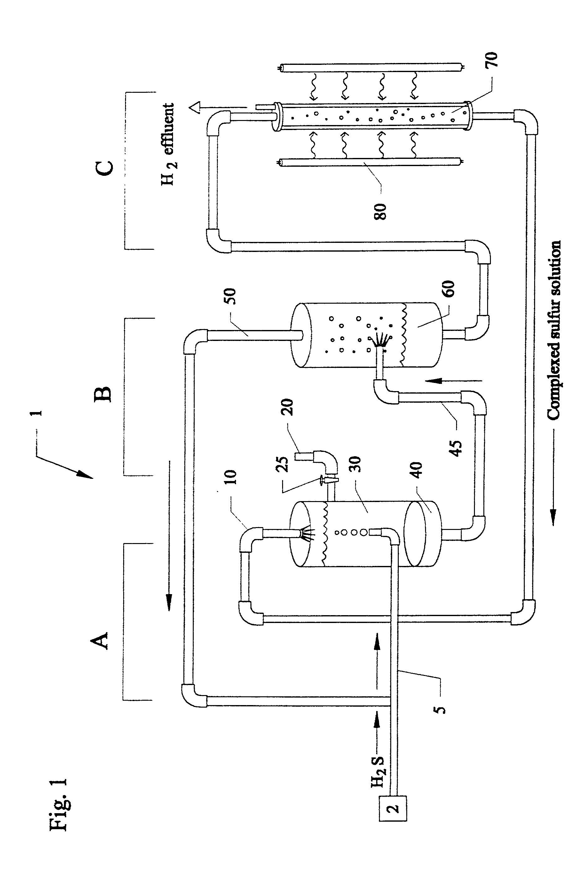
[0020] FIG. 1 is a layout system 1 of the photoelectrochemical particle (PEP) process for H.sub.2S decomposition for sulfur recovery. The system 1 consists of three major units: A, the scrubber and filtration apparatus; B, an outgassing unit such as an H.sub.2S stripper, and the like; and C, the photoreactor. The scrubber used would be akin to a wet scrubber used in gas cleaning applications such as but not limited to the scrubber unit used in U.S. Pat. No. 5,211,923 to Harkness et al., which is incorporated by reference. Hydrogen sulfide H.sub.2S, coming from a source 2 such as a hydrodesulfurization plant, a sour natural gas well an...


PUM


Abstract

A method and system for separating hydrogen and sulfur from hydrogen sulfide (H.sub.2S) gas being produced from oil and gas waste streams. The hydrogen sulfide (H.sub.2S) gas is first passed into a scrubber and filtration unit where it encounters polysufide solution. Elemental sulfur is freed when the H.sub.2S interacts with the solution, the sulfur is filtered through a porous media such as a ceramic frit, and continues to a stripper unit where the excess H.sub.2S is removed from the sulfide solution. The excess H.sub.2S returns to the scrubber and filtration unit, while the sulfide solution passes into a photoreactor containing a semiconductor photocatalyst such as Cadmium Sulfide (CdS), Platinized Cadmium Sulfide, Pt--CdS, Zinc Sulfide, ZnS, Zinc Ferrate, ZnFe.sub.2O.sub.4, Indium Sulfide, In.sub.2S.sub.3, along with a 450-500 nm light source. The sulfide solution inside the photoreactor consisting mainly of bisulfide ion, is oxidatively converted to elemental sulfur and then complexed with excess sulfide ion to make polysulfide ion, while water is reduced to make hydrogen under the action of the light source. Hydrogen percolates out of the photoreactor, while the polysulfide solution is fed back to the scrubber unit where the system operation starts over again for additional hydrogen sulfide gas.

Description

[0001] This invention relates to sulfur recovery from oil and gas refinery waste streams, and in particular to a method and apparatus for sulfur recovery from oil and gas refinery waste streams using semiconductor particulates, where hydrogen sulfide (H.sub.2S) having been absorbed into an alkaline solution is decomposed in a photochemical scheme to yield both sulfur and hydrogen which can be later sold or used internally at a refinery and is a continuation of Provisional Application 60 / 126,036 filed on Mar. 25, 1999, by the same inventors thereof.BACKGROUND AND PRIOR ART[0002] Oil refineries typically pump crude oil from the ground which contains unusable organic sulfur, the latter of which must be separated from the crude oil in order to allow the oil to become a useful product. Typically, the pumped crude oil is treated with hydrogen and a catalyst under a high temperature which decomposes the organic sulfur in the crude oil and releases the sulfur in the form of hydrogen sulfide...

Claims


Application Information

Patent Timeline
IPC IPC(8): C01B3/04C01B17/05
CPCC01B3/04C01B17/05Y02E60/364Y02E60/36Y02P20/133
Inventor LINKOUS, CLOVIS A.MURADOV, NAZIM Z.
Owner UNIV OF CENT FLORIDA
Why Eureka
Try Eureka