Electronic-endoscope light source unit for setting shading period

a technology of electronic endoscope and light source unit, which is applied in the field of electronic endoscope light source unit, can solve the problems of static image quality degradation, mechanical response delay, and change in so as to achieve constant response time of shading shutter

Inactive Publication Date: 2001-11-01
FUJI PHOTO OPTICAL CO LTD
View PDF0 Cites 14 Cited by
  • Summary
  • Abstract
  • Description
  • Claims
  • Application Information

AI Technical Summary

Benefits of technology

0034] Also, the present light source unit makes it possible to form a dynamic image in accordance with the under-image-pickup-device-outputting pixel-mixing read mode and form a static image in accordance with the every-pixel read mode.
0035] According to the above structure, the rotation axis of the fan-shaped shading shutter of the full-closed shading mechanism is set to the V-shape intersection of the opening of the shading mask and the shading shutter rotates from one side toward the other side of the V shape of the opening. However, the diaphragm plate of the diaphragming mechanism linearly move...

Problems solved by technology

However, the above simultaneous electronic endoscope system has a problem that the quality (resolution or color shift) of, particularly, a static image is deteriorated if there is a time shift of {fraction (1/60)} sec between an odd-field signal and an even-field signal for forming a one-frame image and an endoscope or an object to be observed is moved during the time shift...

Method used


Image

  • Electronic-endoscope light source unit for setting shading period
  • Electronic-endoscope light source unit for setting shading period
  • Electronic-endoscope light source unit for setting shading period

Examples


first embodiment

[0052] First Embodiment

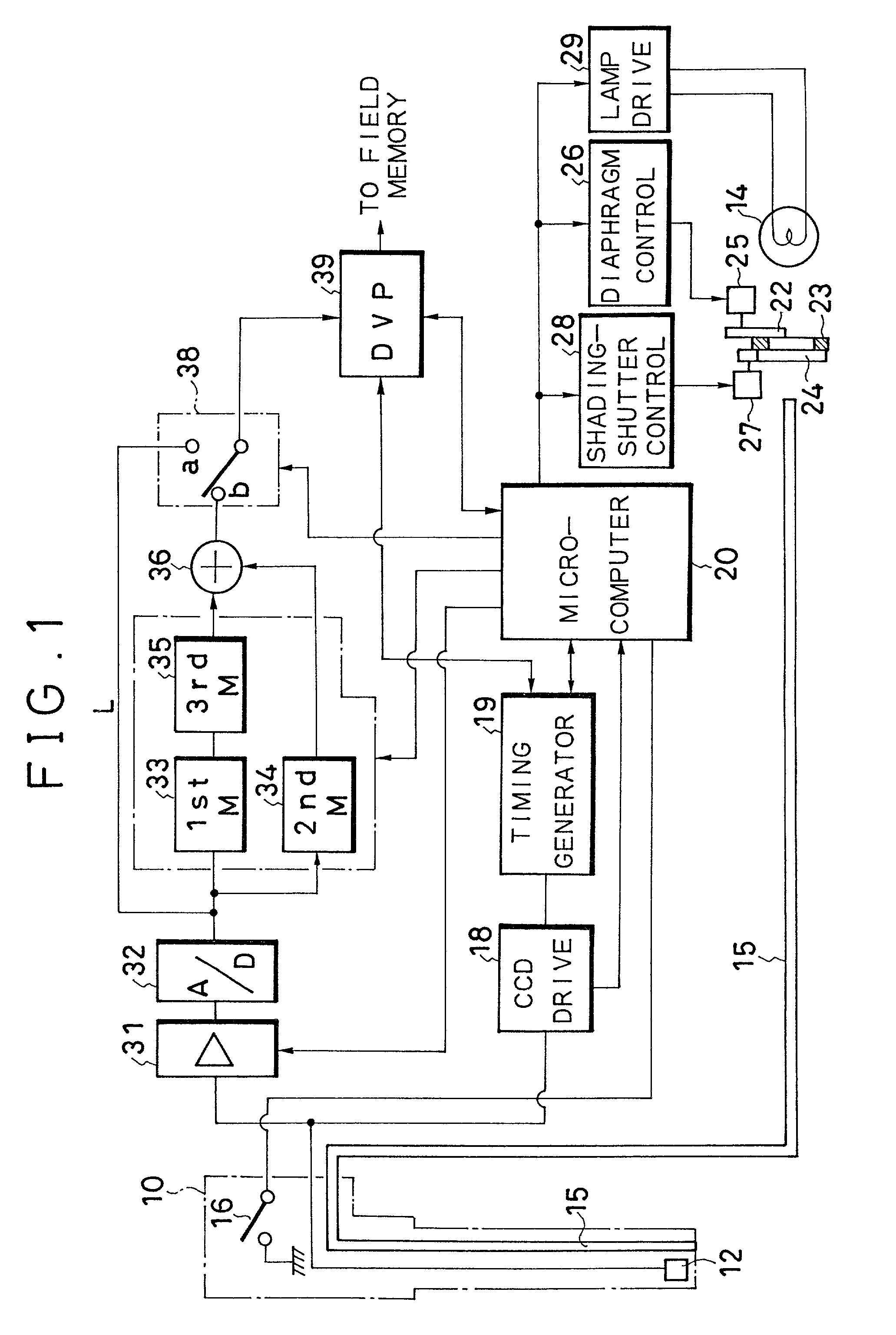
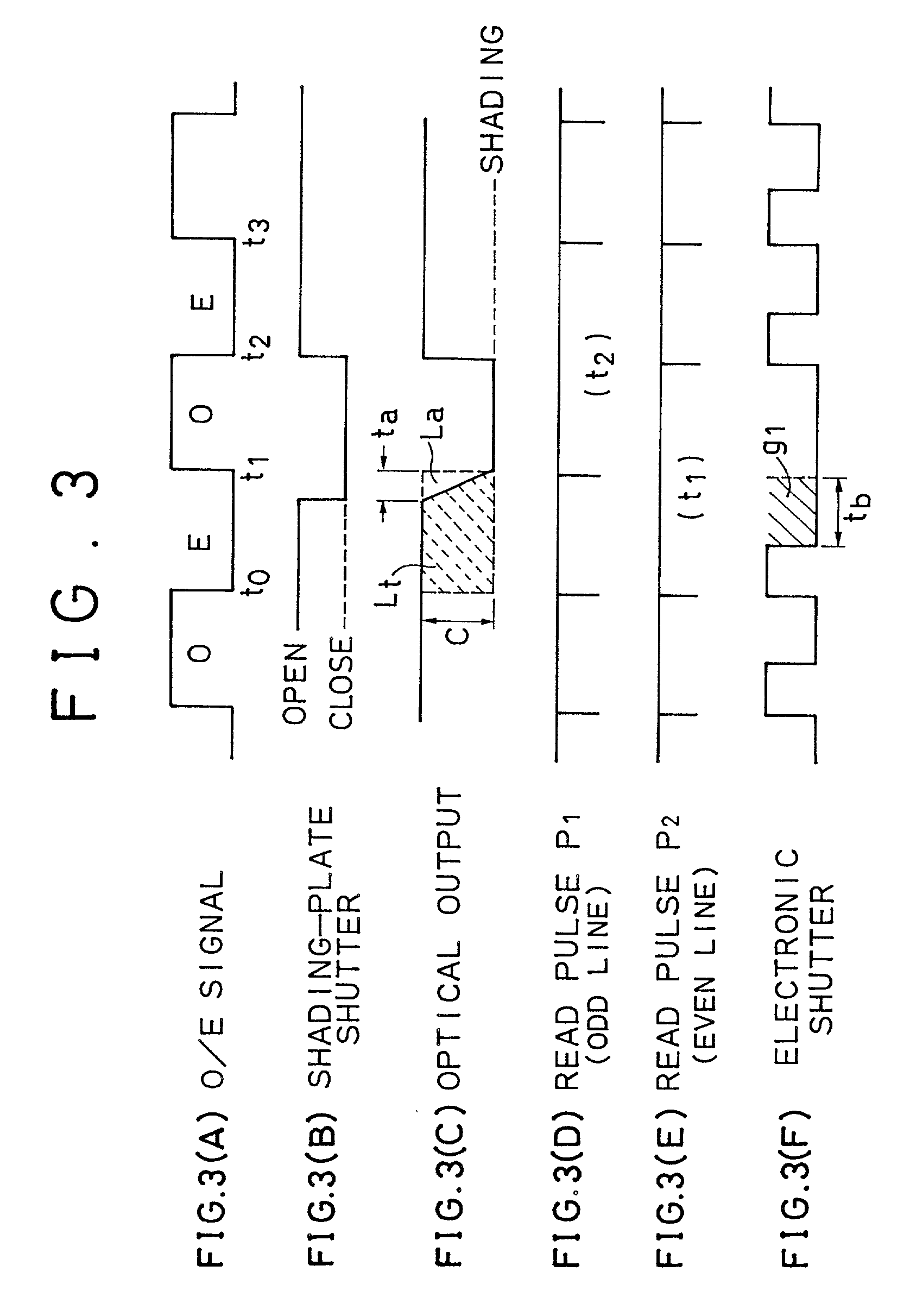
[0053] FIG. 1 shows the structure of an electronic endoscope system to which a light source unit of the present embodiment is applied. The electronic endoscope system is constituted by connecting a scope (electronic endoscope) 10 to a processor unit having an image processing circuit or a light source unit. A CCD 12 provided with the same color filters as those described for FIG. 14 is set to the front end of the scope 10 and a light guide 15 for guiding the light of a light source lamp 14 up to the front end is set to the scope 10. Moreover, a freeze switch 16 for displaying a static image is set to the operating section of the scope 10.

[0054] A CCD driving circuit 18 for driving the CCD 12 is connected to the CCD 12, a timing generator 19 and a microcomputer 20 for performing various types of control are connected to the driving circuit 18, and the operation signal of the freeze switch 16 is input to the microcomputer 20. The CCD driving circuit 18 receives ...

second embodiment

[0081]

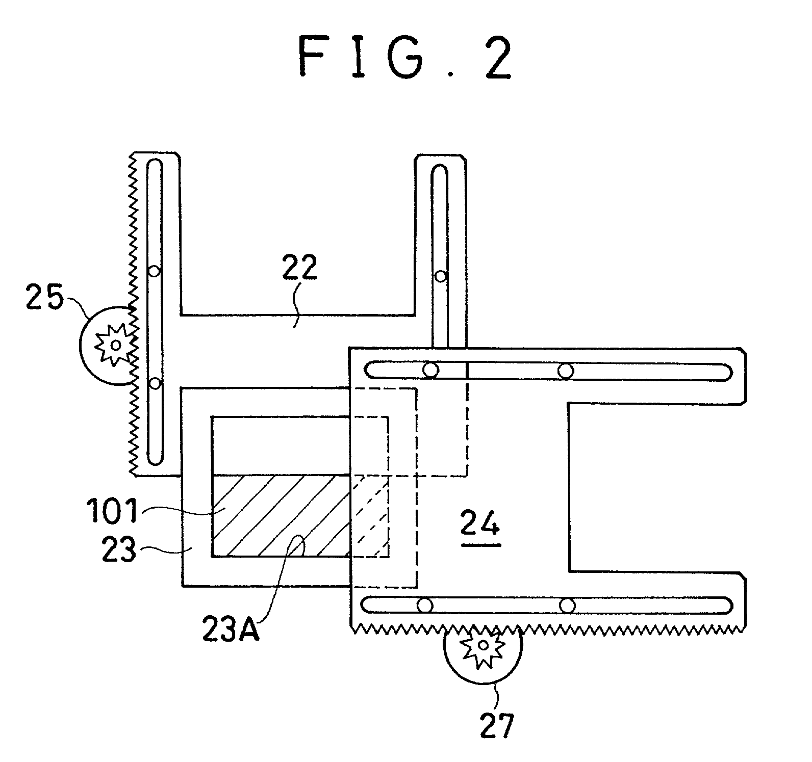
[0082] FIG. 6 shows the second embodiment related to a diaphragming mechanism. This embodiment is provided with a diaphragm vane 3 so as to shade a circular luminous flux (opening) 100 similarly to the case of the conventional diaphragm vane of FIG. 15, in which a shading shutter 42 for shading the luminous flux 100 is horizontally movably set to drive the shading shutter 42 with a motor 43. In this case, the diaphragm vane 3 rotates about a rotation axis 3A to vertically move and the shading shutter 42 horizontally moves so as to almost perpendicularly intersect the moving direction of the vane 3.

[0083] Also according to the above structure, it is possible to keep the response time of the shading shutter 42 almost constant except the time when the shutter is greately diaphragmed and obtain a static image having a stable brightness because the change of insufficient luminous energy due to the response time is controlled.

[0084] This embodiment accurately reproduces the movement...

third embodiment

[0086] Third Embodiment

[0087] FIGS. 7 to 9 show the structure of the electronic endoscope system of the third embodiment. Also in the case of the third embodiment, as shown in FIG. 7, a CCD 12 image-picks up the inside of an object through the irradiation with the light supplied through a light guide 15 and connects with a CCD driving circuit 18, a timing generator 19, and a microcomputer 66 for performing various controls. The CCD driving circuit 18 drives and controls the under-CCD-outputting pixel-mixing read mode for dynamic images and the every-pixel read mode for static images similarly to the case of the first embodiment.

[0088] Moreover, a light source section for supplying light to the light guide 15 is provided with a light source lamp 14, a condenser lens 69, a diaphragm vane 70 for adjusting outgoing luminous energy, a shading shutter (plate) 71 for setting a complete shading period, and a condenser lens 72 are arranged between the lamp 14 and the incoming end of the ligh...


PUM


Abstract

The present invention is a unit for eliminating the fluctuation of luminous energy reduction by keeping the response time of a shading mechanism constant even if a diaphragm opening degree differs when reading every pixel by setting a shading period. This unit is provided with a shading mask having a quadrangular or V-shaped opening and moves a shading shutter in the horizontal direction perpendicular to the vertically moving direction of a diaphragm plate. Therefore, a shading period is set in accordance with the constant response time of the shading shutter and the rate of luminous energy reduction becomes constant. Moreover, a high-quality static image having a stable brightness can be obtained by reading the signal of every pixel obtained by a CCD through one-time exposure while using the shading period and then pixel-mixing signals. Furthermore, it is possible to use the Archimedean spiral for the outer periphery of the diaphragm plate or the shading shutter.

Description

[0001] This application claims the priority of Japanese Patent Application No. 10-96785 filed on Mar. 25, 1998 and Nos. 10-103792 and 10-103793 filed on Mar. 30, 1998 which are incorporated herein by reference.[0002] 1. Field of the Invention[0003] The present invention relates to an electronic-endoscope light source unit, particularly to a structure for adjusting the luminous energy of video signals for reading every pixel by an electronic endoscope for reading the signal of every pixel accumulated in an image pickup device by setting a shading period.[0004] 2. Description of the Prior Art[0005] In the case of an electronic endoscope system, a video signal is formed by reading electric charges accumulated by a photoelectric conversion device in pixels by a CCD (Charge Coupled Device) serving as a solid-state image pickup device. Moreover, in the case of a simultaneous-type electronic endoscope system, color filters are arranged on the CCD in pixels and thereby, a color image can be...

Claims


Application Information

Patent Timeline
IPC IPC(8): A61B1/05H04N5/225H04N5/235
CPCA61B1/05H04N5/2256H04N5/2354H04N2005/2255H04N23/555H04N23/56H04N23/74
Inventor HIGUCHI, MITSURUAYAME, DAISUKEYAMANAKA, KAZUHIROTAKEUCHI, SHINJI
Owner FUJI PHOTO OPTICAL CO LTD
Why Eureka
Try Eureka