Pyrolytic self-cleaning oven

a self-cleaning and pyrolysis technology, applied in the field of self-cleaning domestic ovens, can solve the problem that the control system cannot fix the temperature and time limit only

Inactive Publication Date: 2001-12-20
WHIRLPOOL CORP
View PDF0 Cites 14 Cited by
  • Summary
  • Abstract
  • Description
  • Claims
  • Application Information

AI Technical Summary

Benefits of technology

[0011] In the case the catalyst is used in conjunction with the pyrolytic cleaning of the oven when the cavity of the oven contains a certain amount of soil, over a certain temperature soil start to modify due to Maillard reaction producing gaseous components including CO, hydrocarbons and other volatile components. Those skilled in the art will recognise the Maillard reaction as a well known nonenzymatic reaction browning of foods in the cooking process. These components typically flow out of an oven through an exhaust gas passage, and so pass through the catalyst. When the catalytic material coating on the conductors is at a sufficiently high temperature, a chemical reaction occurs that transforms CO into carbon dioxide, as well as catalytic oxidation of other components, in an exothermic reaction. As a consequence, the temperature of the catalytic material, and accordingly the temperature of the underlying conductor, increases and the resistance of the conductor changes in response to the temperature change. By monitoring this change of resistance or by monitoring power consumption if the catalyst is heated for its activation, the control system of the oven can detect a signal that is a measurement of the concentration of certain components of the exhaust gas in the passage and thus, indirectly, of the stage of the cooking or of the amount of soil remaining inside the cavity in the pyrolytic self-cleaning cycle. The change of catalyst temperature is very rapid in case of even small changes of CO concentration in the oven or in the exhaust gases. When the change of CO concentration is around 100 ppm, the catalyst temperature has a dramatic change, and this sensitiveness is the reason why a control system according to the invention is very reliable and accurate.
[0013] In a further embodiment several layers of net-shaped catalytic elements can be used in order to increase the efficiency of oxidation of CO and other exhaust gases. Moreover the use of a plurality of layers can allow controlling the temperature pattern through the catalyst, such monitoring giving useful information to the electronic controller as far as the stages of cooking or of the pyrolytic self-cleaning cycle are concerned.

Problems solved by technology

In the self-cleaning process the control system can only fix temperature and time limit without any input in term of actual development of self-cleaning process.
As a result, current ovens having a self-cleaning function maintain the oven cavity at high temperatures for a longer time than the real needed time, with obvious drawbacks in term of energy saving and enamel life.

Method used


Image

  • Pyrolytic self-cleaning oven
  • Pyrolytic self-cleaning oven
  • Pyrolytic self-cleaning oven

Examples


Embodiment Construction

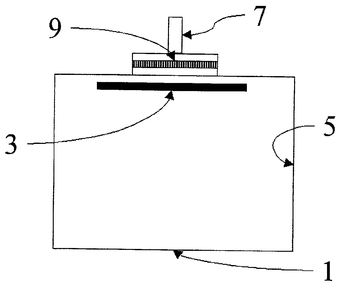
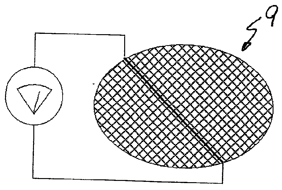
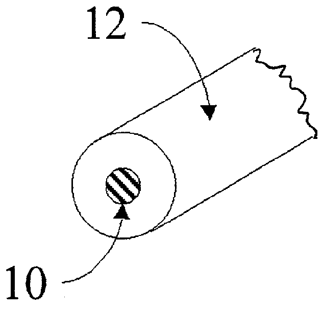
[0023] Referring now to the figures of the drawing, a domestic oven 1 is provided with a usual electrical heater 3 inside its cavity 5. Alternately, a gas burner could be used as the heating source for cooking and pyrolytic self-cleaning. The oven is further provided with an exhaust gas passage 7 in which a catalytic element 9 is placed. According to the invention, the element 9 is made of metal wires 10 coated with a catalytic composition 12 of platinum supported on ceramic material (FIG. 3). At least one of the wires 10 of the element 9 is connected to a circuit for measuring the electrical resistance of the wire. As will be readily understood by one skilled in he art, the circuit may for example comprise a bridge configuration with an operational amplifier.

[0024] In FIG. 4 an embodiment similar to the previous one is disclosed, in which the element 9 is made of metal wires 10a coated with a catalytic composition 12 and in which at least one of such wire 10a is provided with a par...


PUM


Abstract

A pyrolytic self-cleaning oven having a catalytic composition positioned in the oven cavity or exhaust gas passage in order to complete the combustion and / or the oxidation of gases produced by a process carried out inside the oven. The catalytic composition is supported by a ceramic coating on a metal wire. The metal wire is electrically connected to a control system of the oven for controlling the cooking and / or pyrolytic cleaning process. The catalytic composition carried on the metal wire may be part of a net-shaped catalytic element.

Description

[0001] 1. Field of the Invention[0002] The present invention relates to a self-cleaning domestic oven and, more particularly, to a control system for monitoring evolution of a cooking cycle and / or evolution and end of a cleaning cycle in a standard or pyrolytic oven.[0003] The invention relates also to the use of an integrated sensor, placed in exhaust gas passage or into the cavity of the oven.[0004] 2. Description of the Related Art[0005] It is known in the art to control a pyrolytic self-cleaning oven cycle by detecting the temperature by means of temperature sensing elements or probes disposed in the cavity of the oven. U.S. Pat. No. 4,852,544 discloses one of these known methods in which the probes are resistance temperature detectors using platinum probe elements exhibiting positive temperature coefficients. '544 discloses the use of a digital control system for receiving voltage input signals from the temperature sensors and for providing digital pulses or signals to the micr...

Claims


Application Information

Patent Timeline
Patent Type & Authority Applications(United States)
IPC IPC(8): F24C14/02
CPCF24C14/02
Inventor ALLERA, RICCARDOBEGHI, MAURIZIOSCABURRI, ADRIANOCORDA, ANDREA
Owner WHIRLPOOL CORP
Why Eureka
Try Eureka