
Plasma processing apparatus having an evacuating arrangement to evacuate gas from a gas-introducing part of a process chamber

Inactive Publication Date: 2002-01-10
TOKYO ELECTRON LTD
View PDF3 Cites 67 Cited by
  • Summary
  • Abstract
  • Description
  • Claims
  • Application Information

AI Technical Summary

Benefits of technology

[0009] A more specific object of the present invention is to provide a plasma processing apparatus which can apply a high-quality process to an object to be processed by removing impurities from a gas-introducing part of a process chamber.
[0012] In one embodiment of the present invention, the gas-evacuating arrangement may comprise a second vacuum pump connected to the gas-introducing part. That is, the second vacuum pump, which is different from the first vacuum pump, exclusively evacuates the reactant gas remaining in the gas-introducing part, which results in a rapid and efficient evacuation of the reactant gas remaining in the gas-introducing part.
[0023] Accordingly, the reactant gas remaining in the gas-introducing part can be rapidly and efficiently evacuated from the gas-introducing part by the second vacuum pump exclusive provided to the gas-introducing part.
[0025] Accordingly, the reactant gas remaining in the gas-introducing part can be rapidly and efficiently evacuated from the gas-introducing part by the first vacuum pump by a bypass passage that bypasses the process chamber.

Problems solved by technology

However, there is a problem in the conventional plasma processing apparatus in that residual impurities such as a water component cannot be completely removed from inside the process chamber.
However, since the gas-introducing part provided to the process chamber has gas-introducing holes (nozzles) each having a very small diameter, a removal speed of the water component remaining inside the gas-introducing part is low.
The water component remaining inside the gas-introducing part may enter and close the gas-introducing holes, which interrupts the introduction of the reactant gas into the process chamber.
Thus, a yield rate of the object to be processed is deteriorated.
Additionally, if some of the gas-introducing holes are closed, this may deteriorate a uniform distribution of the reactant gas in the process chamber, which may result in an uneven degree of processing of the object to be processed.
Further, if the water component in the gas-introducing holes is ejected into the process chamber, the water component acts as an impurity, which deteriorates a high-quality process to be applied to the object to be processed.

Method used


Image

  • Plasma processing apparatus having an evacuating arrangement to evacuate gas from a gas-introducing part of a process chamber
  • Plasma processing apparatus having an evacuating arrangement to evacuate gas from a gas-introducing part of a process chamber
  • Plasma processing apparatus having an evacuating arrangement to evacuate gas from a gas-introducing part of a process chamber

Examples


Embodiment Construction

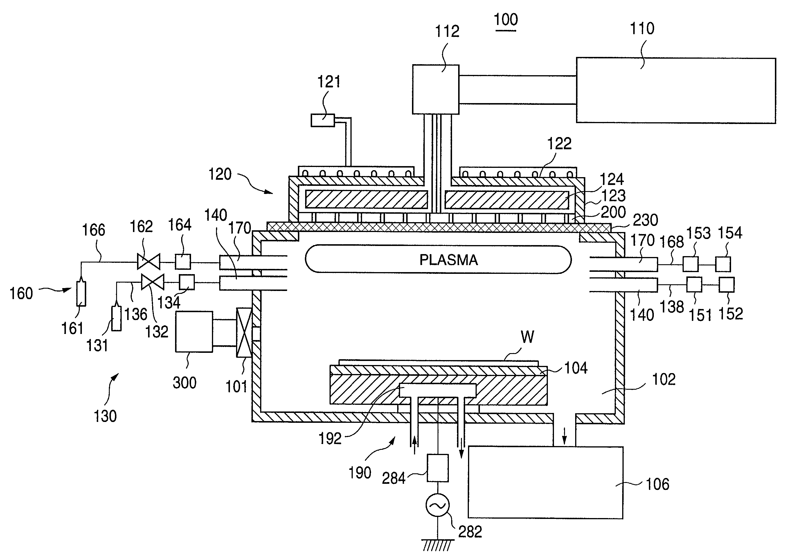
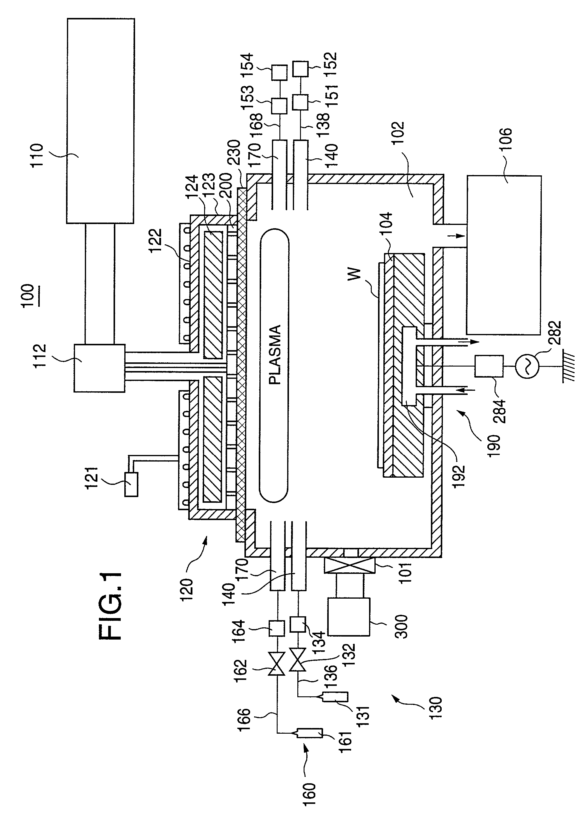
[0048] A description will now be given, with reference to FIG. 1, of a first embodiment of the present invention. FIG. 1 is an illustration of a structure of a microwave plasma processing apparatus 100 according to the first embodiment of the present invention. The first embodiment of the present invention is specifically related to an evacuating arrangement to evacuate gas from a gas-introducing part provided in a process chamber of the microwave plasma processing apparatus 100.

[0049] The microwave plasma processing apparatus 100 shown in FIG. 1 comprises: a gate valve 101 connected to a cluster tool 300; a process chamber 102 which can accommodate a susceptor 104 on which an object to be processed such as a semiconductor wafer or an LCD substrate; a high-vacuum pump 106 connected to the process chamber; a microwave supply source 110; an antenna member 120; and gas supply systems 130 and 160. It should be noted that a control system of the plasma processing apparatus 100 is not ill...


PUM

PropertyMeasurementUnit
Pressureaaaaaaaaaa
Densityaaaaaaaaaa
Frequencyaaaaaaaaaa

Abstract

A plasma processing apparatus can apply a high-quality process to an object to be processed by removing impurities from a gas-introducing part of a process chamber. The gas-introducing part connected to the process chamber so as to introduce a reactant gas into the process chamber. A first vacuum pump is connected to the process chamber so as to evacuate gas from the process chamber so that the process chamber is maintained at a negative pressure. A gas-evacuating arrangement is connected to the gas-introducing part so as to exclusively evacuate the reactant gas from the gas-introducing part. The gas-evacuating arrangement includes a second vacuum pump directly connected to the gas introducing part or a bypass passage connecting the gas-introducing par to the first vacuum pump by bypassing the process chamber.

Description

[0001] 1. Field of the Invention[0002] The present invention relates to plasma processing apparatuses and, more particularly, to a plasma processing apparatus having a gas-introducing part, which introduces a reactant gas into a process chamber.[0003] 2. Description of the Related Art[0004] In recent years, a plasma processing apparatus is used to perform a film deposition process, an etching process or an ashing process in a manufacturing process of semiconductor devices since the semiconductor devices have become more densified and a finer structure. For example, in a typical microwave plasma processing apparatus, a 2.45 GHz microwave is introduced into a process chamber through a slot electrode. An object to be processed such as a semiconductor wafer or an LCD substrate is placed inside the process chamber, which is maintained under a negative pressure environment by a vacuum pump. Additionally, a reactant gas is also introduced into the process chamber so that the process gas is...

Claims


Application Information

Patent Timeline
IPC IPC(8): B01J19/08C23C16/44C23C16/455C23C16/511H01J37/32H01L21/20H01L21/302H01L21/3065H01L21/31
CPCC23C16/4408C23C16/4412C23C16/45561C23C16/45565C23C16/4558C23C16/511H01J37/32192H01J37/3244H01J37/32834H01J2237/022H01L21/3145H01L21/3185H01L21/02263H01L21/0217H01L21/02238H01L21/02247H01L21/02252
Inventor HONGO, TOSHIAKIOSAWA, TETSU
Owner TOKYO ELECTRON LTD
Learn More