VCO circuit with wide output frequency range and PLL circuit with the VCO circuit

a technology of vco circuit and vco circuit, which is applied in the direction of electrial characteristics varying frequency control, pulse generator, pulse technique, etc., can solve the problems of increasing design load in order to output synchronized clocks, difficult to broaden oscillating frequency range, and difficult to realize pll with a wide lock rang

Inactive Publication Date: 2002-04-04
MITSUBISHI ELECTRIC CORP
View PDF0 Cites 21 Cited by
  • Summary
  • Abstract
  • Description
  • Claims
  • Application Information

AI Technical Summary

Problems solved by technology

As a result, many of PLL circuits are required to be incorporated, which leads to increase in design load in order to output synchronized clocks corresponding to a wide frequency range.
Therefore, since a configuration is adopted of controlling an oscillating operation of the ring oscillator by a current value, it is difficult to broaden an oscillating frequency range.
For this reason, it is also difficult to realize a PLL with a wide lock rang

Method used


Image

  • VCO circuit with wide output frequency range and PLL circuit with the VCO circuit
  • VCO circuit with wide output frequency range and PLL circuit with the VCO circuit
  • VCO circuit with wide output frequency range and PLL circuit with the VCO circuit

Examples


second embodiment

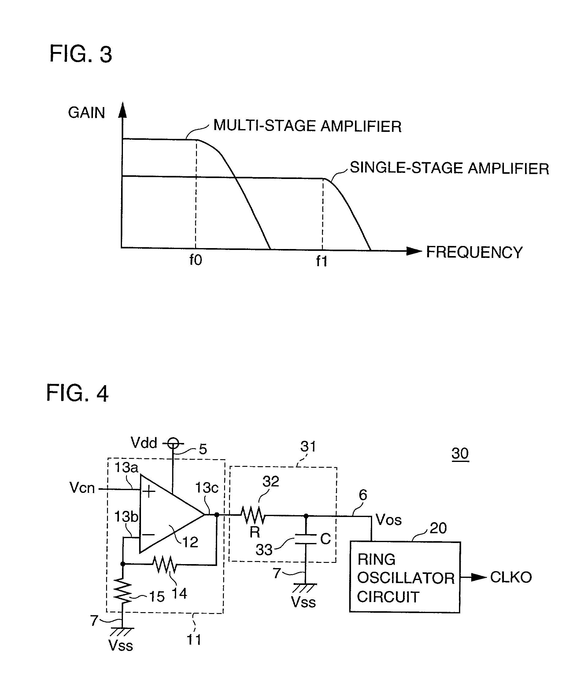
[0062] Referring to FIG. 4, a voltage-controlled oscillating circuit 30 according to the second embodiment of the present invention differs from the voltage-controlled oscillating circuit 10 shown in FIG. 2 in that the circuit 30 further includes: a filter circuit 31 coupled with the bias voltage line 6.

[0063] The filter circuit 31 has a resistance element 32 coupled in series with the bias voltage line 6; and a capacitor 33 coupled between the bias voltage line 6 and the ground line 7. If a resistance value of the resistance element 32 and a capacitance value of the capacitor 33 are R and C, respectively, by definition, a cut-off frequency of the filter circuit is given by fc=1 / (2.pi..multidot.R.multidot.C). The filter circuit 31 is provided in order to remove a high frequency component of the bias voltage Vos, that is noise, and further stabilize an oscillating frequency fosc of the ring oscillator circuit 20. A configuration and operation of the other constituents combined of the...

third embodiment

[0065] Referring to FIG. 6, a voltage-controlled oscillating circuit 40 according to the third embodiment of the present invention differs from the voltage-controlled oscillating circuit 10 shown in FIG. 2 in that the circuit 40 further includes: a filter circuit 35 coupled with the power source line 5 in addition to the configuration of the circuit 10.

[0066] The filter circuit 35 is a low pass filter including: a resistance element 36 coupled in series with the power source line 5; and a capacitor 37 coupled between the power source line 5 and the ground line 7. The filter circuit 35 is provided in order to remove noise in the power source voltage Vdd supplied to the operational amplifier 12. A configuration and operation of the other constituents combined of the voltage-controlled oscillating circuit 40 are similar to the voltage-controlled oscillating circuit 10; therefore, neither of detailed descriptions thereof is repeated.

[0067] Next, description will be given of an influence...

fourth embodiment

[0077] In the fourth embodiment, description will be given of a variation of configuration of an operational amplifier circuit constituted by the operational amplifier 12 in the bias voltage generating circuit 11.

[0078] Referring to FIG. 9, a voltage-controlled oscillating circuit 50 according to the fourth embodiment of the present invention differs from the voltage-controlled oscillating circuit 10 shown in FIG. 2 comparing therewith in that a bias voltage generating circuit 51 is provided instead of the bias voltage generating circuit 11. A configuration and operation of the other constituents combined of the voltage-controlled oscillating circuit 50 are similar to the voltage-controlled oscillating circuit 10; therefore, neither of descriptions thereof is repeated.

[0079] The output terminal 13c of the operational amplifier 12 is coupled directly with the inverting input terminal 13b. On the other hand, to the input terminal 13a of the operational amplifier 12, the control voltag...


PUM


Abstract

A voltage-controlled oscillating circuit according to the present invention includes: a drive voltage generating circuit outputting a bias voltage according to a control voltage; and a ring oscillator circuit receiving supply of the bias voltage to operate. The drive voltage generating circuit generates the bias voltage using a feedback circuit formed by an operational amplifier receiving supply of a power source voltage to operate. Therefore, an influence of a high frequency component overlapped on the power source voltage, that is an influence of noise, is suppressed, thereby enabling stable generation of an output clock having a small variation in phase.

Description

[0001] 1. Field of the Invention[0002] The present invention relates to a voltage-controlled oscillating circuit, and more particularly, to a voltage-controlled oscillating circuit capable of altering an oscillating frequency according to a control voltage and to a phase-locked loop circuit, a so-called PLL circuit, equipped with the voltage-controlled oscillating circuit.[0003] 2. Description of the Background Art[0004] In order to cooperatively operate a plurality of internal circuits implemented on the same system, employed are phase-locked loop circuits (PLL circuit) each generating a synchronized clock. Especially, in recent years, an LSI (Large Scale Integrated Circuit) has experienced progress toward its higher speed operation in company with miniaturization; as a result, a margin in phase shift between a clock of the entire system on which an LSI is implemented and an internal clock of the LSI has become narrowed, which in turn, has enhanced a chance of usage of a PLL circui...

Claims


Application Information

Patent Timeline
IPC IPC(8): H03K3/03H03L7/00H03L7/093H03L7/099
CPCH03L7/0995H03L7/093H03L7/00
Inventor ITOOTA, YOSHIYUKI
Owner MITSUBISHI ELECTRIC CORP
Why Eureka
Try Eureka