Process and device for reducing the ignition voltage of plasmas operated using pulses of pulsed power

a technology of pulsed power and plasma, which is applied in the direction of electrodes, ion implantation coatings, chemical vapor deposition coatings, etc., can solve the problems of inability to arbitrarily reduce the electrical power applied, inability to apply arbitrary reduction, and inability to achieve the effect of reducing the electrical power applied

Inactive Publication Date: 2002-04-18
FRAUNHOFER GESELLSCHAFT ZUR FOERDERUNG DER ANGEWANDTEN FORSCHUNG EV
View PDF0 Cites 3 Cited by
  • Summary
  • Abstract
  • Description
  • Claims
  • Application Information

AI Technical Summary

Problems solved by technology

Because of the required stability of the coating plasma, an arbitrary reduction of the electrical power applied is not possible because if the power density is too low, it causes inhomogeneities in the coating plasma and therefore layer inhomogeneities and instability of the coating process.
This is particularly problematic in the case of larger cathode arrangements.
This, however, results in a considerable loss of effectiveness.
The deciding disadvantage of this arrangement lies in the fact that, due to pulse-off times during re-ignition of the discharge on the target, a high ignition voltage results.
If the pulse-off times are increased and the pulse-on times are decreased, a very high plasma density on the sputtering target will indeed be achieved at the same average electric power; however, as a result of the long pulse-off time the ignition voltage increases to values that lie substantially above the burning voltage of the plasma and may amount to several kilovolts.
This can again cause damage in the various switching arrangements and undesired arcs.
The problem described above generally occurs in plasmas that are pulsed at medium frequency.

Method used


Image

  • Process and device for reducing the ignition voltage of plasmas operated using pulses of pulsed power
  • Process and device for reducing the ignition voltage of plasmas operated using pulses of pulsed power
  • Process and device for reducing the ignition voltage of plasmas operated using pulses of pulsed power

Examples


Embodiment Construction

[0028] The particulars shown herein are by way of example and for purposes of illustrative discussion of the embodiments of the present invention only and are presented in the cause of providing what is believed to be the most useful and readily understood description of the principles and conceptual aspects of the present invention. In this regard, no attempt is made to show structural details of the present invention in more detail than is necessary for the fundamental understanding of the present invention, the description taken with the drawings making apparent to those skilled in the art how the several forms of the present invention may be embodied in practice.

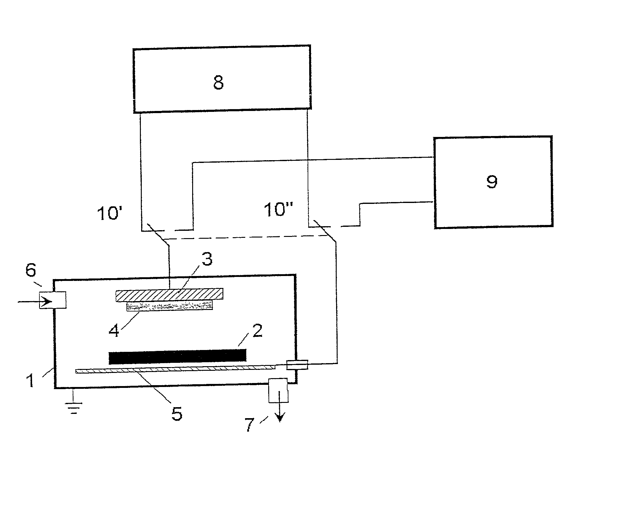
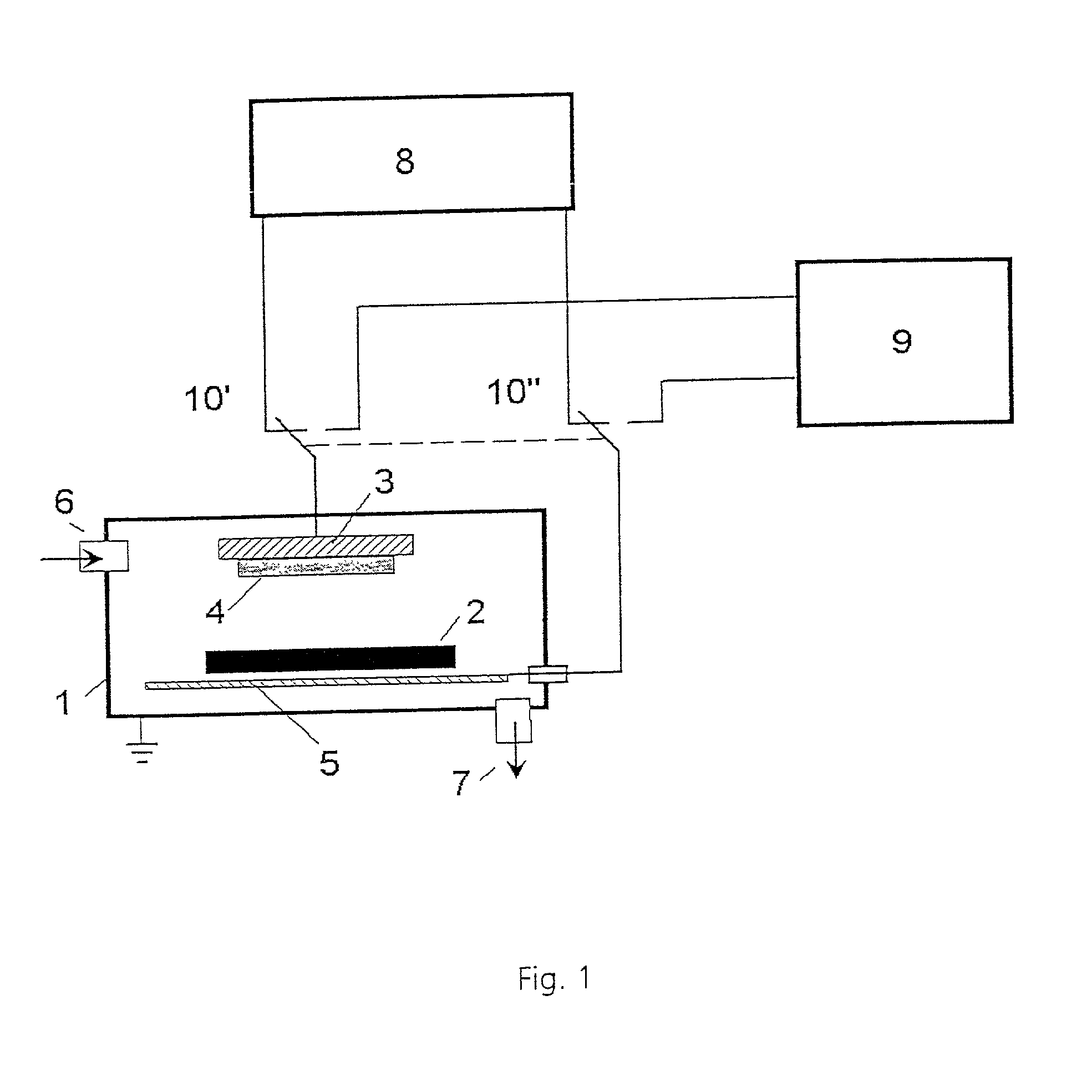
[0029] FIG. 1 illustrates a sputtering device which is located in a vacuum chamber or vessel 1 of a vacuum coating installation, i.e., one which is used for depositing thin silver layers, e.g., between approximately 1 nm-10 nm, on a substrate 2 made of glass. The sputtering system includes a Magnetron 3 acting as a catho...


PUM

PropertyMeasurementUnit
frequencyaaaaaaaaaa
frequencyaaaaaaaaaa
frequencyaaaaaaaaaa

Abstract

Process and device for reducing an ignition voltage of power pulses in plasmas operated in a pulsed manner with long pulse-off times. The process includes generating a power pulsed plasma at a pulse duty factor, the pulse duty factor being a ratio of pulse-on time to pulse-off time, and at least before the beginning of the pulse-on time of the power pulses, producing charge carriers using an additional plasma discharge at a lower power than that of the power pulses. The device includes a vacuum chamber including at least one pump system, an arrangement for producing plasma, the arrangement including at least one anode and at least one cathode, an energy source connected to the cathode and the anode which cab be pulsed in the frequency range of between approximately 10 Hz to approximately 1 MHz, and a mechanism for one of producing an additional plasma discharge.

Description

[0001] The present application claims priority under 35 U.S.C. .sctn.119 of German Patent Application No. 100 51 508.8, filed on Oct. 18, 2000, the disclosure of which is expressly incorporated by reference herein in its entirety.[0002] 1. Field of the Invention[0003] The invention relates to a process and to related devices for reducing the ignition voltage of plasmas operated using pulses of pulsed power with a long pulse-off time. Such plasmas are used for treating substrates in, e.g., atomization processes which utilize vacuum coating devices, in plasma activation as part of various coating processes, and in other processes utilizing vacuum technology. Cathode atomization processes, also known as sputtering, represent a primary area of application for pulsed plasmas within the coating technology. With their aid, many things such as components, tools, partially finished products, as well as finished products which are used in optics and mechanical engineering. Many parts, such as...

Claims


Application Information

Patent Timeline
Patent Type & Authority Applications(United States)
IPC IPC(8): C23C14/35
CPCC23C14/35
Inventor LIST, MATTHIASKRAUSE, UWE
Owner FRAUNHOFER GESELLSCHAFT ZUR FOERDERUNG DER ANGEWANDTEN FORSCHUNG EV
Why Eureka
Try Eureka