
Synthetic silica glass molding method, synthetic silica glass molding apparatus, and synthetic silica glass

a technology molding method, which is applied in the direction of glass pressing apparatus, glass making apparatus, manufacturing tools, etc., can solve the problems of shrinkage generated when the system is cooled down to room temperature, the conventional molding method suffers, and the residual gas bubbles of synthetic silica glass cannot be used as optical components

Inactive Publication Date: 2002-05-02
NIKON CORP
View PDF0 Cites 16 Cited by
  • Summary
  • Abstract
  • Description
  • Claims
  • Application Information

AI Technical Summary

Benefits of technology

[0023] Another object of the present invention is to provide a synthetic silica glass molding method and apparatus that achieve a sufficient uniformity in transmissivity and suppress crystallization and irregularities in concentration in the resulting synthetic silica glass member.
[0025] Another object of the present invention is to provide a synthetic silica glass, which possesses a sufficient uniformity in transmissivity and suppresses crystallization and irregularities in concentration and which is suitable for use in reticle (photo-mask) substrates and lens materials of image-focusing optical systems.

Problems solved by technology

Furthermore, since a thermal expansion caused by generation of heat in its substrate is a major problem, a silica glass synthesized by the flame hydrolysis method, which has good durability as well as a small coefficient of thermal expansion, is used.
However, the conventional molding methods suffer from the following drawbacks.
First, gas bubbles are generated in the synthetic silica glass bulk during the press-molding at high temperatures, and these gas bubbles remain in the synthetic silica glass in large quantities after the molding.
Synthetic silica glass containing such large quantities of residual gas bubbles cannot be used as optical members.
Further, in cases where a synthetic silica glass bulk is press-molded in a molding vessel, the amount of shrinkage generated when the system is cooled down to the room temperature after the high temperature molding considerably differs between the synthetic silica glass bulk and the molding vessel.
Consequently, in the conventional method, undesirable stresses are applied to the synthetic silica glass bulk and the molding vessel.
This often leads to generation of cracks in the press-molded synthetic silica glass and various damages to the molding vessel.
As a result, depending upon the molding temperature, undesirable recesses and projections are formed on the surface of the resulting synthetic silica glass, thereby resulting in generation of cracks and / or a loss in transmissivity.
The temperature inside the synthetic silica glass during the treatment is not always controlled to be constant.
Moreover, the non-uniformity in the inside temperature causes uneven concentration in the resulting glass member.
This problem is significant, particularly for synthetic silica glass members into which components that alter the refractive index have been introduced.
Such irregularity in concentration led to a large degradation in optical properties in some cases.
Also, in cases where a synthetic silica glass is subjected to a heat / press molding treatment in a graphite molding vessel, the optical characteristics of the resulting synthetic silica glass member (especially the uniformity of the in-plane transmissivity) are often degraded.
If a synthetic silica glass member having such an insufficient uniformity in the in-plane transmissivity is incorporated in an exposure apparatus as a member, the image-focusing performance of the exposure apparatus significantly degrades, which is undesirable.
In some cases, however, this measure was found not to be always sufficient.
As a result of further research conducted in an effort to solve the problems, the present inventors discovered that the insufficient results occur when there exists flexing in the elastic member (plate-form felt member made of carbon fibers) that is used on the upper surface of the synthetic silica glass bulk.
If the partial pressure of the inert gas inside the electric furnace 20 is less than about 0.05 MPa, the synthetic silica glass tends to volatilize, so that there is an increased tendency toward generation of gas bubbles inside the synthetic silica glass bulk, which is undesirable.

Method used


Image

  • Synthetic silica glass molding method, synthetic silica glass molding apparatus, and synthetic silica glass
  • Synthetic silica glass molding method, synthetic silica glass molding apparatus, and synthetic silica glass
  • Synthetic silica glass molding method, synthetic silica glass molding apparatus, and synthetic silica glass

Examples


working example 1

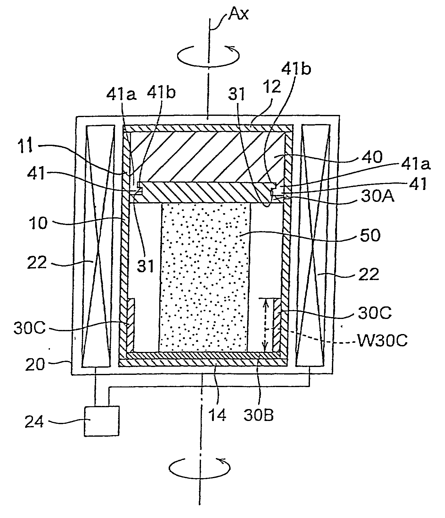
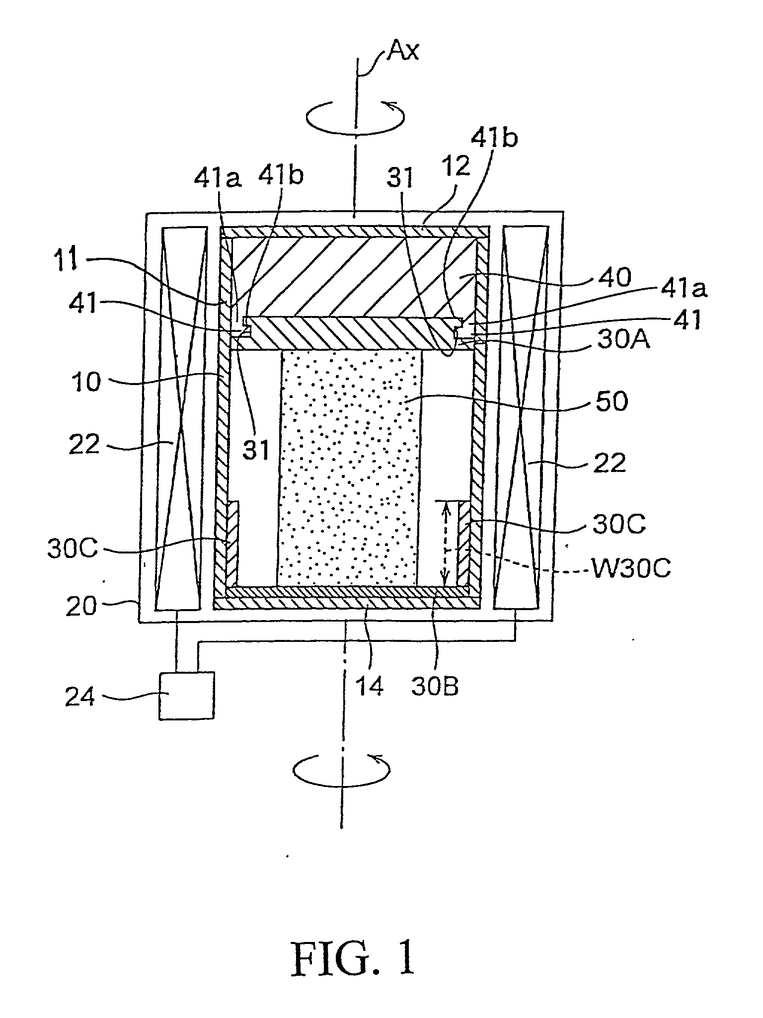
[0077] In Working Example 1, the crucible shape of the graphite molding vessel 10 was a cylindrical shape with a diameter of 220 mm, and a graphite molding vessel in which the engaging parts 41 and engaged parts 31 of the present invention were installed was used. Furthermore, inside this graphite molding vessel 10, elastic members 30A, 30B and 30C made of carbon fibers manufactured by Nippon Carbon Co. Ltd., sold under the trademark "CARBOLON FELT" (CARBOLON FELT is a registered trademark) were respectively disposed in the same manner as shown in FIG. 1.

[0078] Furthermore, the respective thicknesses of the carbon fiber elastic members 30B and 30C were 2.about.3 mm and 10 mm, and the bulk density was set at 0.1 g / cm.sup.3 in all cases. Moreover, the elastic member 30A was obtained by superimposing two elastic members similar to the elastic member 30B. In other words, the thickness of the elastic member 30A was set at 4.about.6mm.

[0079] Next, a cylindrical synthetic silica glass bulk...

working example 2

[0081] In Working Example 2, a synthetic silica glass was obtained by press-molding in the same manner as in Working Example 1, except that the treatment pressure was set at 0.6 MPa, the temperature was set at 1775.degree. C., and the retention time was set at 60 min.

working example 3

[0082] In Working Example 3, a synthetic silica glass was obtained by press-molding in the same manner as in Working Example 1, except that the crucible shape of the graphite molding vessel 10 was 160 mm square, and the treatment pressure was set at 0.2 MPa.


PUM

PropertyMeasurementUnit
porosityaaaaaaaaaa
temperatureaaaaaaaaaa
thicknessaaaaaaaaaa

Abstract

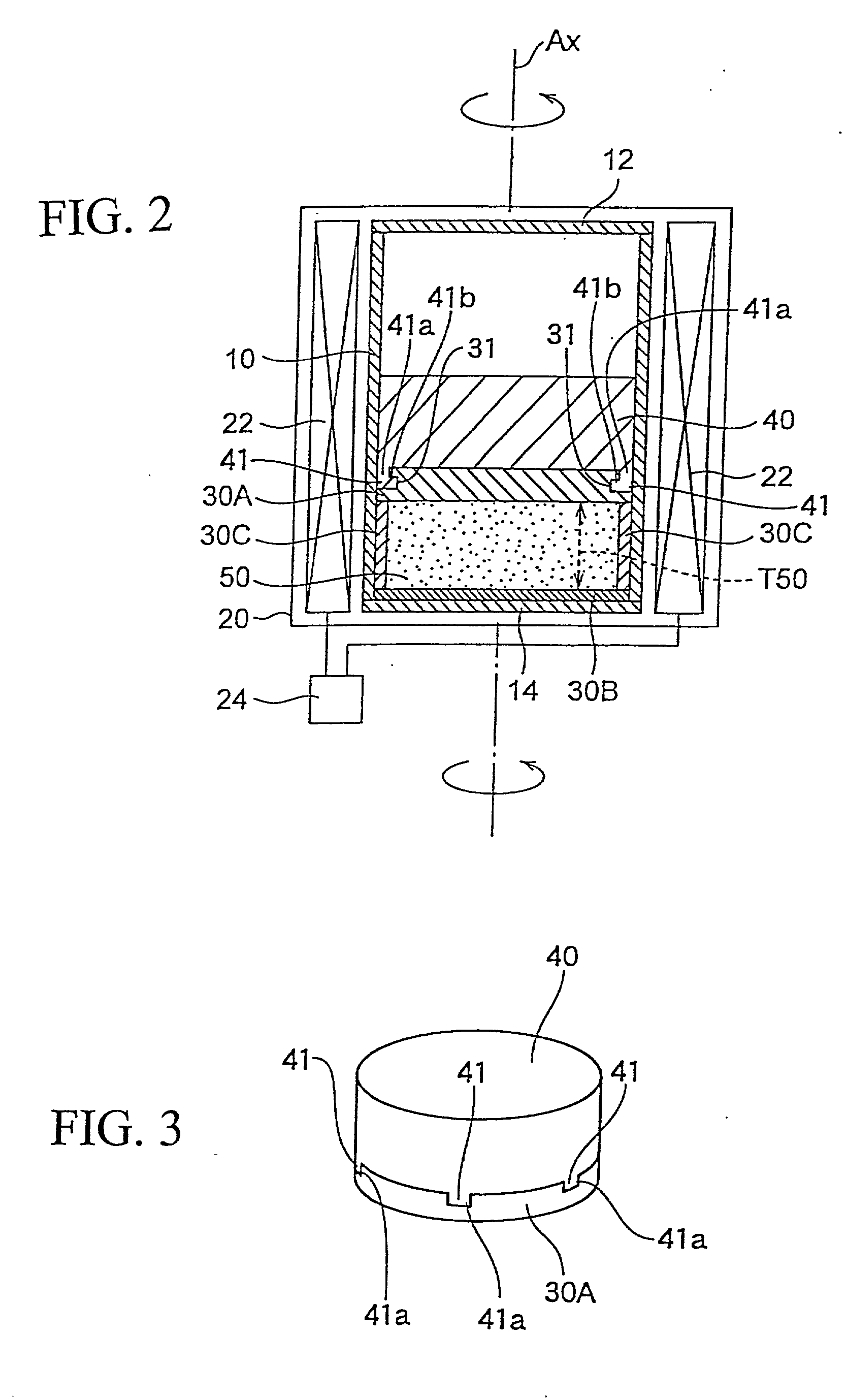
A method is provided for molding a synthetic silica glass member. The method includes accommodating a synthetic silica glass bulk inside a molding vessel; interposing an elastic member having a ventilating property between a pressing member and the synthetic silica glass bulk; providing a fastener for fastening at least peripheral edge portions of the elastic member to the pressing member; and pressing the synthetic silica glass bulk against the molding vessel by the pressing member in a high-temperature condition to mold the synthetic silica glass bulk into a synthetic silica glass member having a shape conforming to a shape of the space defined by the pressing member and the molding vessel, the synthetic silica glass bulk being pressed in such a manner that the pressing member and the elastic member tightly fasten to each other through the fastener.

Description

[0001] This application claims the benefit of Japanese Applications No. 2000-242638 and No. 2000-242639, both filed in Japan on Aug. 10, 2000, which are hereby incorporated by reference.[0002] 1. Field of the Invention[0003] The present invention relates to a method for molding a synthetic silica glass bulk into a synthetic silica glass of a desired shape by heating and pressing, a synthetic silica glass molding apparatus, and a synthetic silica glass member that is molded by such a method and apparatus. In particular, the present invention relates to a synthetic silica glass member suitable for use in optical members, such as reticles (photomasks), substrates, and image-focusing optical systems.[0004] 2. Discussion of the Related Art[0005] The present invention concerns synthetic silica glass members suitable for use in optical members, such as reticles (photomasks), substrates, and image-focusing optical systems. Such a synthetic silica glass member is molded into a desired shape ...

Claims


Application Information

Patent Timeline
Patent Type & Authority Applications(United States)
IPC IPC(8): C03B19/14C03B23/00C03B23/049
CPCC03B19/1469C03B23/0493C03B23/0013
Inventor FUJIWARA, SEISHIJINBO, HIROKIKOMINE, NORIO
Owner NIKON CORP
Learn More