Non-absorptive electro-0ptical glazing structure employing composite infrared reflective polarizing filter

Inactive Publication Date: 2002-07-04
REVEO
View PDF0 Cites 65 Cited by
  • Summary
  • Abstract
  • Description
  • Claims
  • Application Information

AI Technical Summary

Problems solved by technology

While conventional forms of glazing serves many useful functions, such forms are not without problems.
While electromagnetic radiation is broad-band in nature, it is the ultraviolet light component thereof which causes molecular decomposition in various types of plastic material and inorganic dyes, which results in color fading.
The energy transmitted through the glass window is typically absorbed by furnishings or structures within the interior environment, and often becomes trapped therewithin causing an increase in interior temperature.
However, as window blind is mounted within the interior of the building or transportation environment, electromagnetic radiation is allowed transmit through the window, raise the temperature within the internal environment, and thus increase thermal loading on cooling systems during the hot weather season.
Also, the operation of window blinds requires mechanical or electromechanical controls which tend to be bulky and expensive to manufacture, install and maintain.
The major disadvantages thereof are reduction in interior light, loss of visibility, and extra care required in cleaning.
Moreover, prior art electromagnetic window films are incapable of changing from transmissive during winter months to reflective during summer months in order to effectively use electromagnetic radiation for dynamic tem

Method used


Image

  • Non-absorptive electro-0ptical glazing structure employing composite infrared reflective polarizing filter
  • Non-absorptive electro-0ptical glazing structure employing composite infrared reflective polarizing filter
  • Non-absorptive electro-0ptical glazing structure employing composite infrared reflective polarizing filter

Examples


embodiment 10

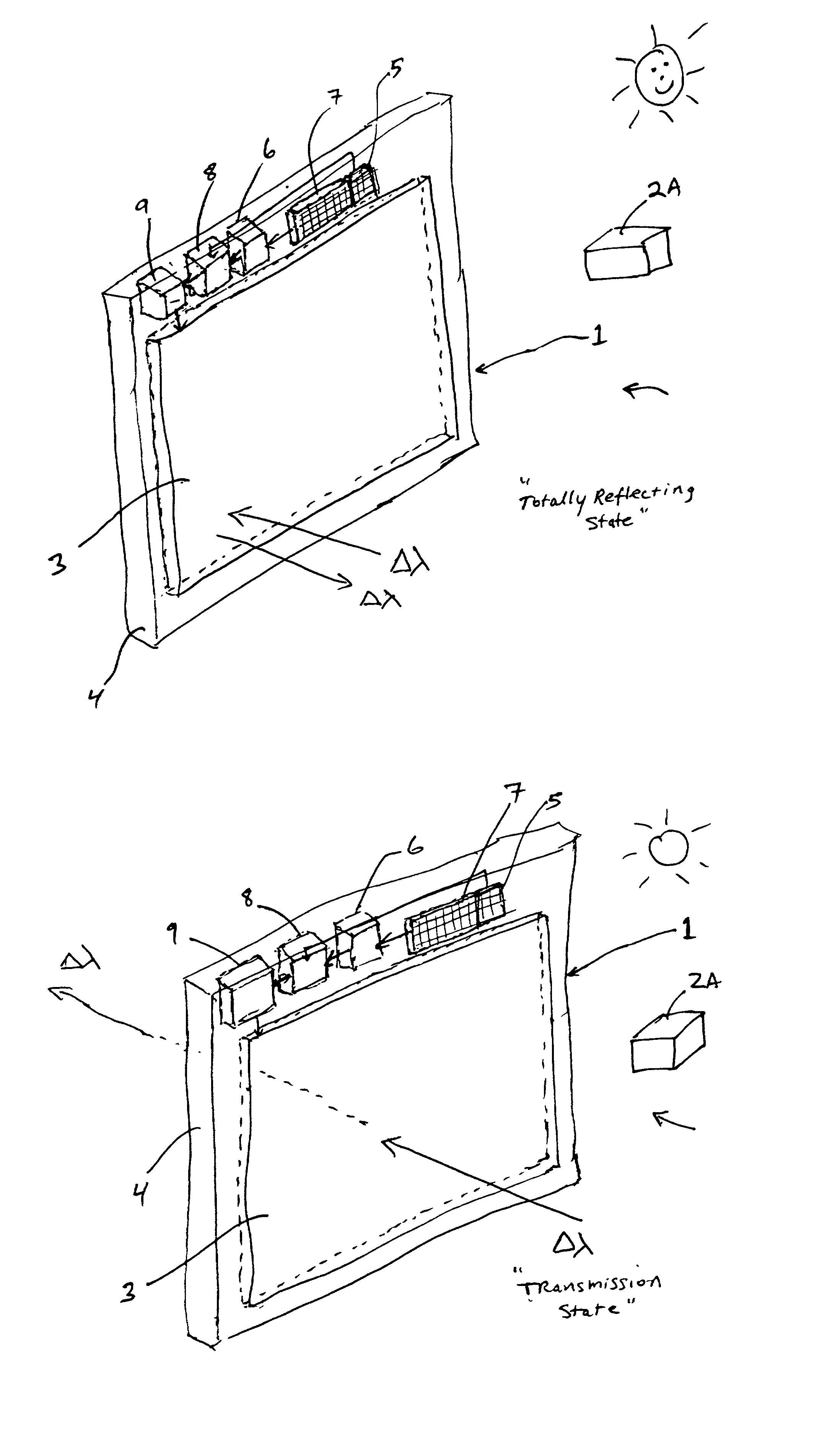
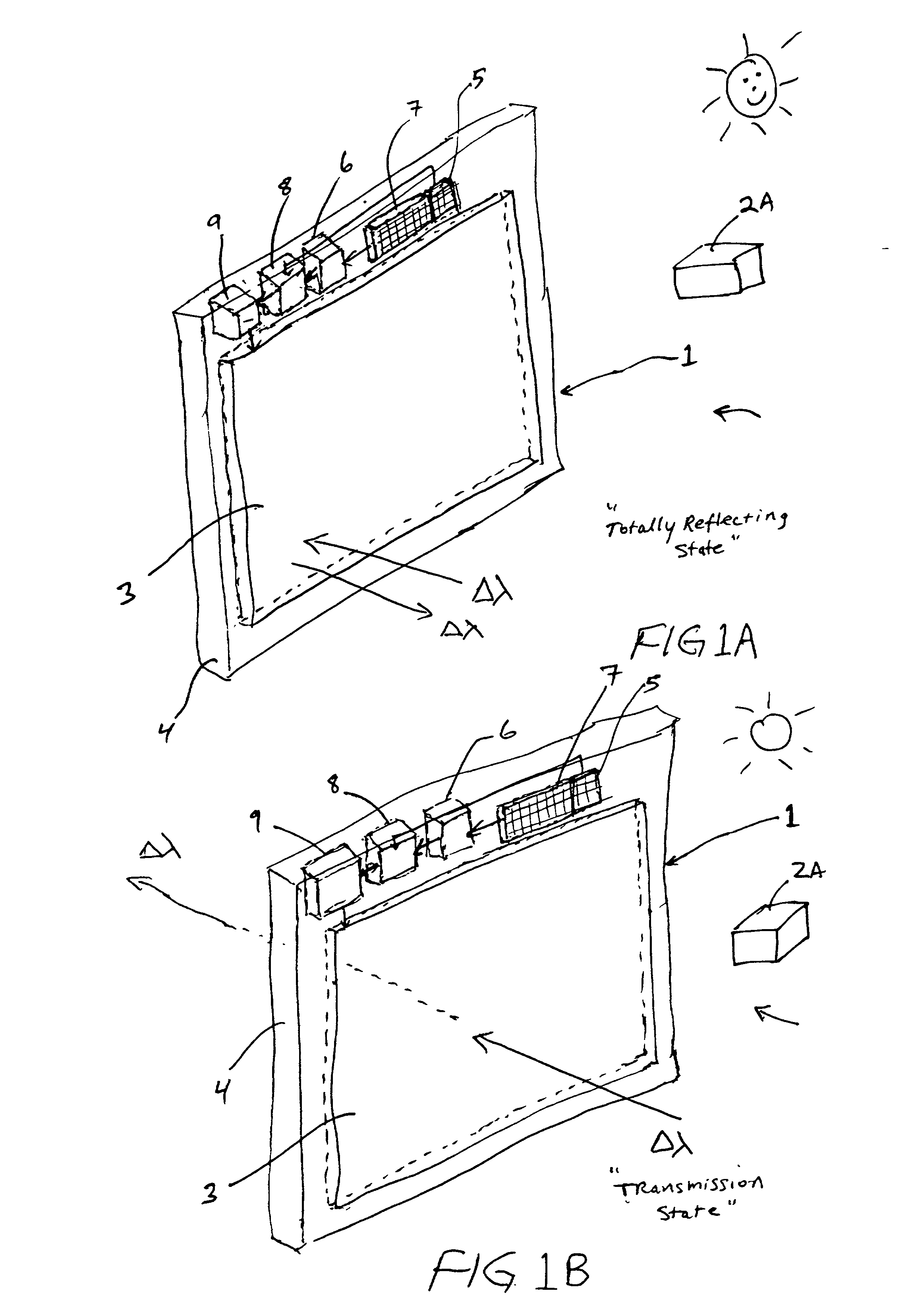
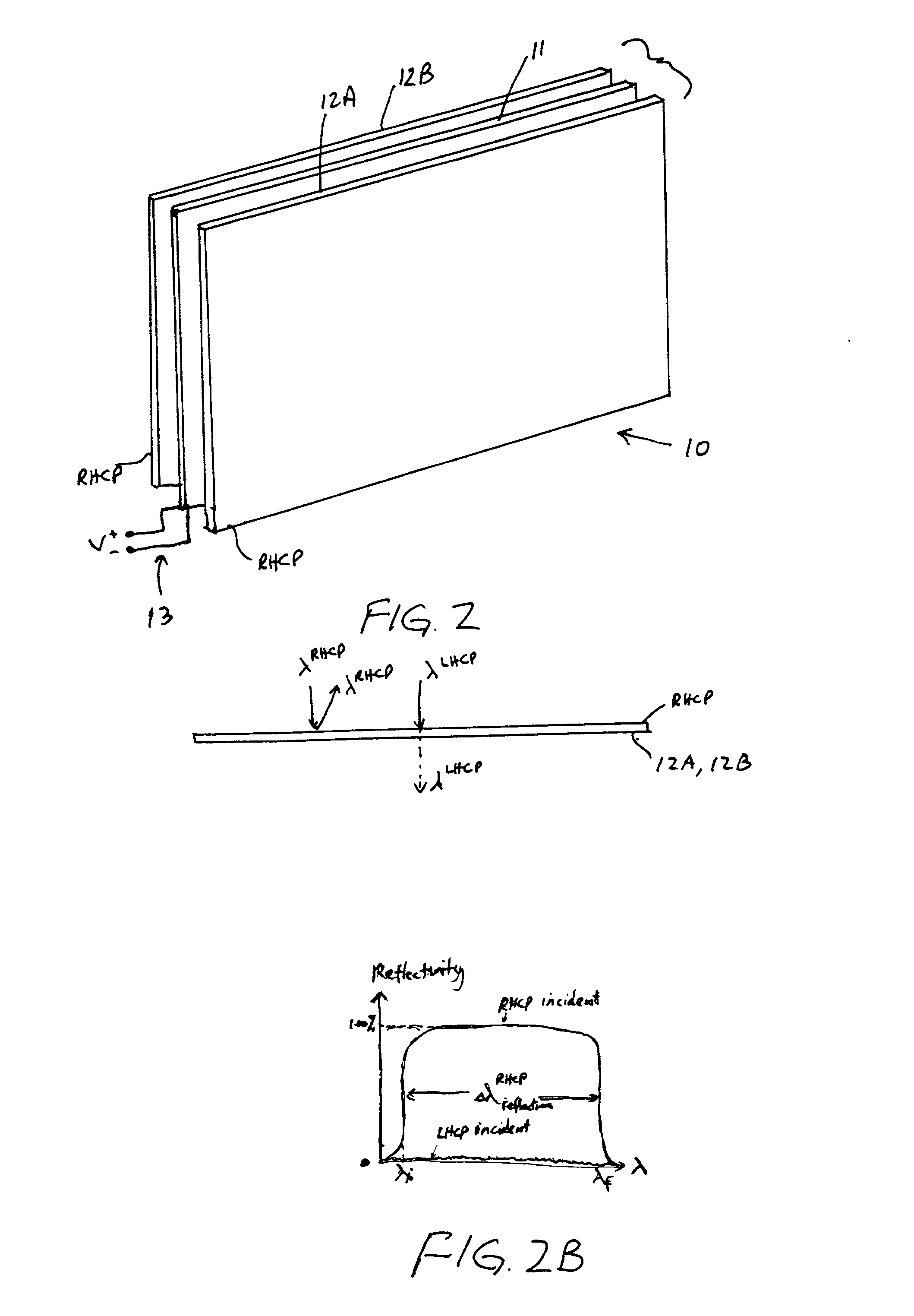
[0165] The first illustrative embodiment of the electro-optical glazing structure hereof will be described with reference to FIGS. 2 through 3B. As shown in FIG. 2, the electro-optical glazing structure of the first illustrative embodiment 10 comprises: an electrically-active .pi.-phase retardation panel 11 interposed between a pair of electrically-passive right-hand circularly polarized (RHCP) electromagnetic radiation reflecting panels 12A and 12B, respectively, for imparting a .pi.-phase retardation to electromagnetic radiation transmitted therethrough in response to optical-state control voltages applied across the electrically-active .pi.-phase retardation panel 11; and

[0166] electrically conductive means 13 for applying optical-state control voltages to the electrically-active .pi.-phase retardation panel 11. Preferably, the electro-optical glazing structure of FIG. 2 is mounted within a frame structure as described in connection with the generalized embodiment shown in FIGS. ...

first embodiment

[0176] In FIG. 2C, the .pi.-phase retardation panel 11 is shown along with a specification of its various states of operation. As shown, when a non-zero voltage (e.g. 20 Volts) is applied across the phase retardation panel, 0-phase retardation is imparted to electromagnetic radiation transmitted therethrough. When a control voltage of zero volts is applied across the phase retardation panel, it imparts a .pi.-phase retardation to electromagnetic radiation transmitted therethrough having a wavelength within its operating band .DELTA..lambda..sub.x which is typically 300-1000 nanometers.

second embodiment

[0177] In FIG. 2D, the .pi.-phase retardation panel is shown along with a specification of its states of operation. As shown, when a control voltage of zero volts is applied across this retardation panel, it imparts a O-phase shift to electromagnetic radiation having a wavelength within its operating band which is typically 350 nanometers, whereas .pi.-phase retardation is imparted to such electromagnetic radiation when a non-zero voltage (e.g. 5-50 Volts) is applied thereacross. For wavelengths outside of the operating band, a phase shift other than .pi.-radians is imparted to incident electromagnetic radiation when a non-zero voltage is applied.

[0178] Physically interfacing the subcomponent panels of the electro-optical glazing structure of FIG. 2 can be achieved using conventional lamination techniques well known in the glazing art.

[0179] The operation of the glazing structure of FIG. 2 will now be described with reference to FIGS. 3A and 3B, where the .pi.-phase retardation pane...


PUM

PropertyMeasurementUnit
Fractionaaaaaaaaaa
Fractionaaaaaaaaaa
Transparencyaaaaaaaaaa

Abstract

Electro-optical glazing structures having total-reflection and semi-transparent and totally-transparent modes of operation which are electrically-switchable for use in dynamically controlling electromagnetic radiation flow in diverse applications.

Description

RELATED CASES[0001] This is a Continuation-in-part of: copending application Ser. No. 08 / 805,603 entitled "Electro-optical Glazing Structures Having Total-reflection And Transparent Modes Of Operation For Use In Dynamical Control Of Electromagnetic Radiation" filed Feb. 26, 1997; copending application Ser. No. 08 / 739,467 entitled "Super Broadband Reflective Circularly Polarizing Material And Method Of Fabricating And Using Same In Diverse Applications", by Sadeg M. Faris and Le Li filed Oct. 29, 1996, which is a Continuation-in-Part of copending application Ser. No. 08 / 550,022 entitled "Single Layer Reflective Super Broadband Circular Polarizer and Method of Fabrication Therefor" by Sadeg M. Faris and Le Li filed Oct. 30, 1995; copending application Ser. No. 08 / 787,282 entitled "Cholesteric Liquid Crystal Inks" by Sadeg M. Faris filed Jan. 24, 1997, which is a Continuation of application Ser. No. 08 / 265,949 filed Jun. 2, 1994, which is a Divisional of application Ser. No. 07 / 798,881...

Claims


Application Information

Patent Timeline
IPC IPC(8): C09B67/00C09D11/02C09D11/16C09K19/00C09K19/52E06B9/24F24J2/40G01D11/28G02B5/30G02B27/00G02F1/1334G02F1/1335G02F1/13357G02F1/1347G02F1/137G02F1/139
CPCB82Y15/00C09B67/0098C09D11/037C09D11/17C09K19/00C09K19/52E06B9/24E06B2009/2464F24J2/407G01D11/28G02B5/3016G02B26/02G02B27/0093G02F1/1334G02F1/133514G02F1/133536G02F1/13362G02F1/133621G02F1/13471G02F1/13718G02F1/1393G02F2001/133543G02F2001/133623H04N2213/008Y02B10/20Y02E10/40F24S50/80G02F1/133543G02F1/133623
Inventor FARIS, SADEG M.LI, LELI, JIAN-FENG
Owner REVEO
Why Eureka
Try Eureka