Clutch control system in continuously variable transmission system for vehicle

a technology of continuously variable transmission system and clutch control system, which is applied in the direction of clutches, mechanical equipment, gearboxes, etc., can solve the problems of affecting the transmission performance of the clutch, the ratio of the toroidal type continuously variable transmission cannot be controlled in some cases, and the durability could be degraded to a great exten

Inactive Publication Date: 2002-07-04
HONDA MOTOR CO LTD
View PDF0 Cites 28 Cited by
  • Summary
  • Abstract
  • Description
  • Claims
  • Application Information

AI Technical Summary

Problems solved by technology

In order to control the ratio of a toroidal type continuously variable transmission, such as that disclosed in the above-mentioned Japanese Patent Application Laid-open No. 10-196759, an electronically controlled device such as a solenoid valve is used, but if the electronic control system fails, the ratio of the toroidal type continuously variable transmission cannot be controlled in some cases.
If such a failure occurs when the vehicle is stationary, then when the vehicle is starting, a load that changes the ratio of the toroidal type continuously variable transmission beyond the L...

Method used


Image

  • Clutch control system in continuously variable transmission system for vehicle
  • Clutch control system in continuously variable transmission system for vehicle
  • Clutch control system in continuously variable transmission system for vehicle

Examples


first embodiment

[0041] the present invention is explained below by reference to FIGS. 1 to 19.

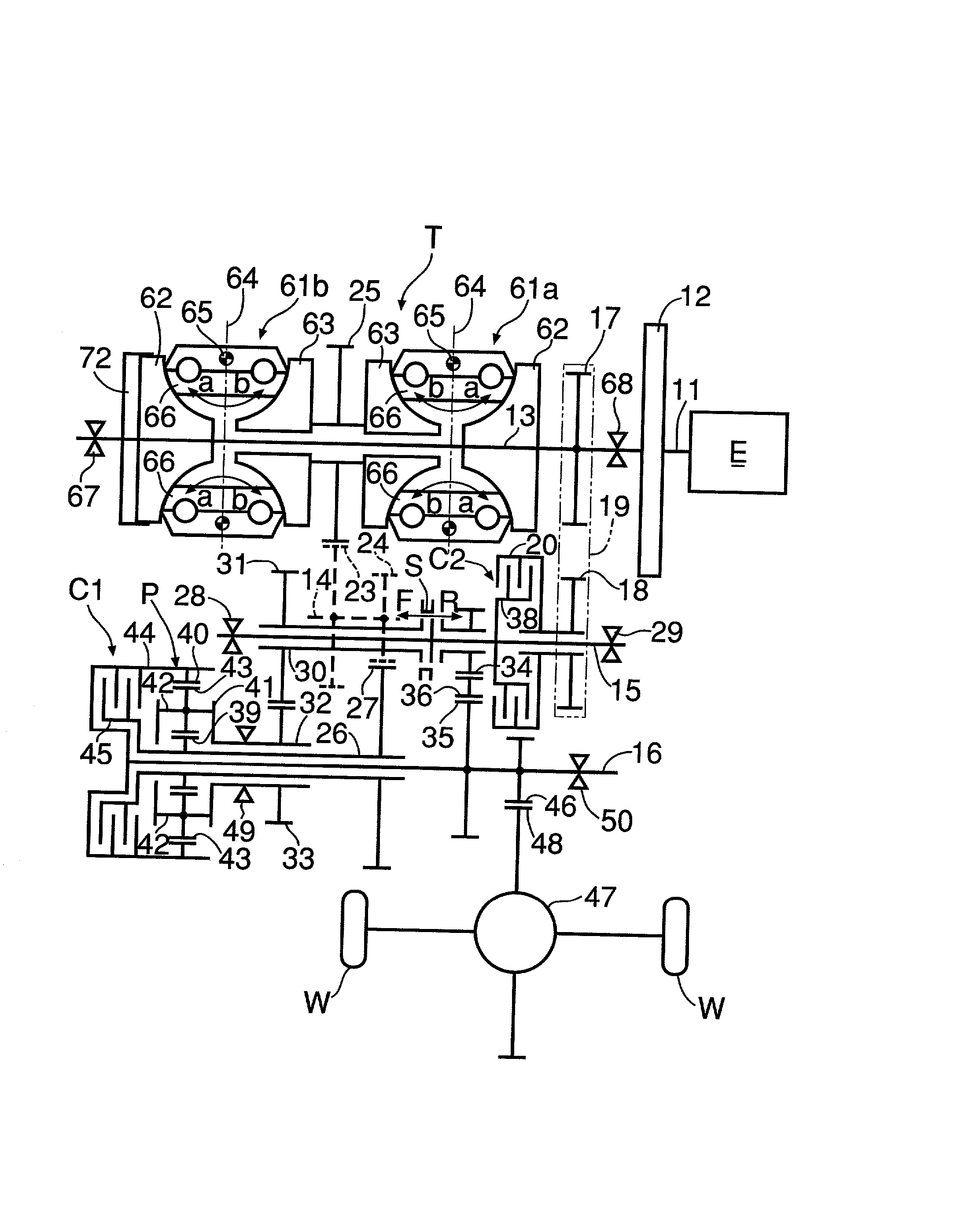
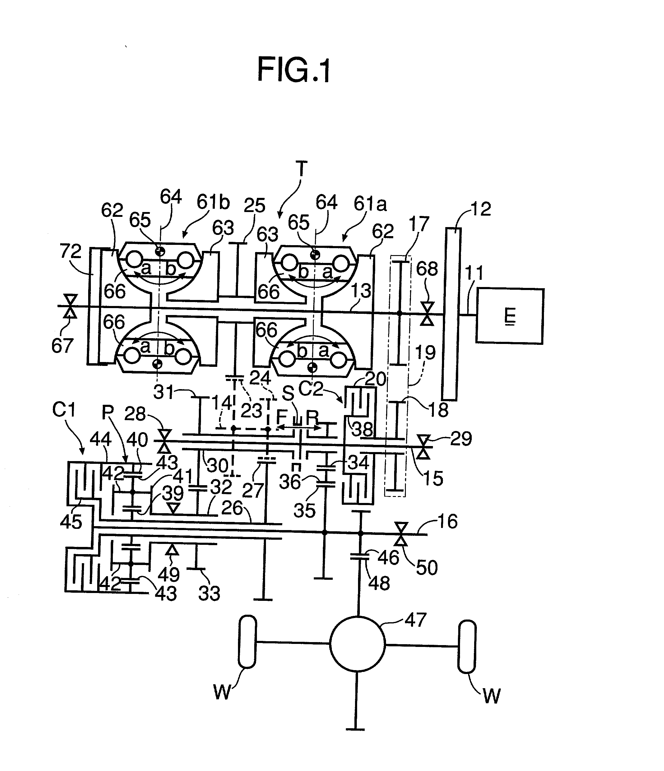
[0042] As shown in FIG. 1 and FIGS. 3 to 5, a continuously variable transmission system for an automobile includes a toroidal type continuously variable transmission T, a single pinion type planetary gear train P, a forward drive clutch C1 (hereinafter called a first clutch C1), which is a wet type multiplate clutch, and a reverse start and torque split clutch C2 (hereinafter called a second clutch C2), which is a wet type multiplate clutch. A crankshaft 11 of an engine E is connected to an input shaft 13 of the toroidal type continuously variable transmission T via a damper 12. Placed parallel to the input shaft 13 of the toroidal type continuously variable transmission T are a first shaft 14, a second shaft 15 and a third shaft 16. The first clutch C1 is provided on the left end of the third shaft 16, and the second clutch C2 is provided on the right end of the second shaft 15. A drive sprocket 17 is fix...

third embodiment

[0106] the present invention is now explained by reference to FIG. 22.

[0107] The continuously variable transmission systems of the first and second embodiments are suitable for front-engined front wheel drive vehicles in which the engine E is transversely mounted. However, the continuously variable transmission system of the present embodiment is suitable for a front-engined rear wheel drive vehicle in which the engine E is longitudinally mounted. The components of the present embodiment that correspond to those in the first and second embodiments are denoted using the same reference numerals and symbols.

[0108] A first shaft 131 and a second shaft 132 are coaxially placed with an input shaft 13 of a toroidal type continuously variable transmission T. The first shaft 131 rotates integrally with the input shaft 13, and the second shaft 132 is connected to driven wheels W (not illustrated). A third shaft 133 and a fourth shaft 134 are placed in parallel to the first shaft 131 and the s...


PUM


Abstract

An engine is connected to a sun gear of a planetary gear train via a toroidal type continuously variable transmission; driven wheels are connected to a ring gear of the planetary gear train; and the sun gear and the ring gear are connected to each other by a first clutch. A shifter can connect a second clutch, which is connected to the engine, to a carrier of the planetary gear train or to the driven wheels. When the vehicle is started forward when a failure has occurred, by controlling the engagement force of the first clutch on the basis of the rotational rate of the engine and the ratio of the toroidal type continuously variable transmission and controlling the engagement force of the second clutch on the basis of the rotational rate of the engine while the second clutch is connected to the carrier by the shifter, it is possible to prevent the ratio of the toroidal type continuously variable transmission from changing beyond the LOW ratio or the OD ratio and generating an excessive load.

Description

[0001] 1. Field of the Invention[0002] The present invention relates to a continuously variable transmission system for a vehicle employing a combination of a continuously variable transmission and a planetary gear train and, in particular, to a clutch control system therein.[0003] 2. Description of the Related Art[0004] Such a continuously variable transmission system for a vehicle is known in Japanese Patent Application Laid-open No. 10-196759.[0005] In accordance with this continuously variable transmission system for a vehicle, when the vehicle is traveling at a low speed the engine torque is transmitted to the driven wheels via a toroidal type continuously variable transmission alone, and when the vehicle is traveling at a high speed the engine torque is transmitted to the driven wheels via both the toroidal type continuously variable transmission and a planetary gear train, and a wide range of ratios that cannot be achieved by use of the toroidal type continuously variable tra...

Claims


Application Information

Patent Timeline
IPC IPC(8): F16H3/54F16H15/38F16H37/02F16H37/08F16H61/12F16H61/662
CPCF16H37/086F16H61/12F16H61/6648F16H2037/088F16H2061/6618
Inventor OOYAMA, KAZUO
Owner HONDA MOTOR CO LTD
Why Eureka
Try Eureka