Liquid crystal information displays

a technology of information display and liquid crystal, applied in the direction of instruments, chemistry apparatus and processes, thin material processing, etc., can solve the problems of low brightness, low contrast, quite high energy consumption, and substantial light loss due to absorption

Inactive Publication Date: 2002-08-08
NITTO DENKO CORP
View PDF17 Cites 22 Cited by
  • Summary
  • Abstract
  • Description
  • Claims
  • Application Information

AI Technical Summary

Problems solved by technology

The general drawback of devices of this kind is low brightness, low contrast and quite high energy consumption.
In each of these there are substantial losses of light due to absorption, as well as due to reflection at the boundary between the layers.
In addition, the known devices have limited viewing angle.
The drawback of the known displays is their low brightness and low contrast, which is due to the absence of optical coordination of all elements in the system, which leads to substantial losses.
For liquid crystal information displays, radiation reflected at the boundaries between functional layers will constitute a loss leading to worsening of the quality of a display.
In a complicated device with large number of layers having substantially different refraction coefficients, the losses of energy due to reflection may reach substantial amounts.
Besides that, for the reflective liquid crystal displays, radiation reflected from the boundaries between the functional layers will lead to glare, which will substantially worsen displaying contrast.

Method used


Image

  • Liquid crystal information displays
  • Liquid crystal information displays

Examples


Embodiment Construction

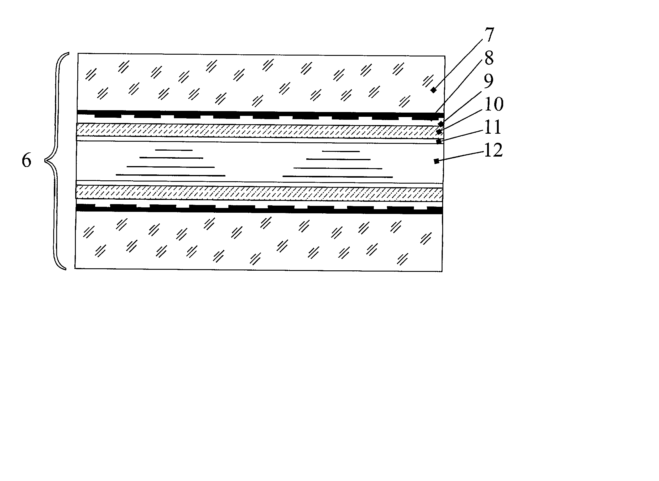
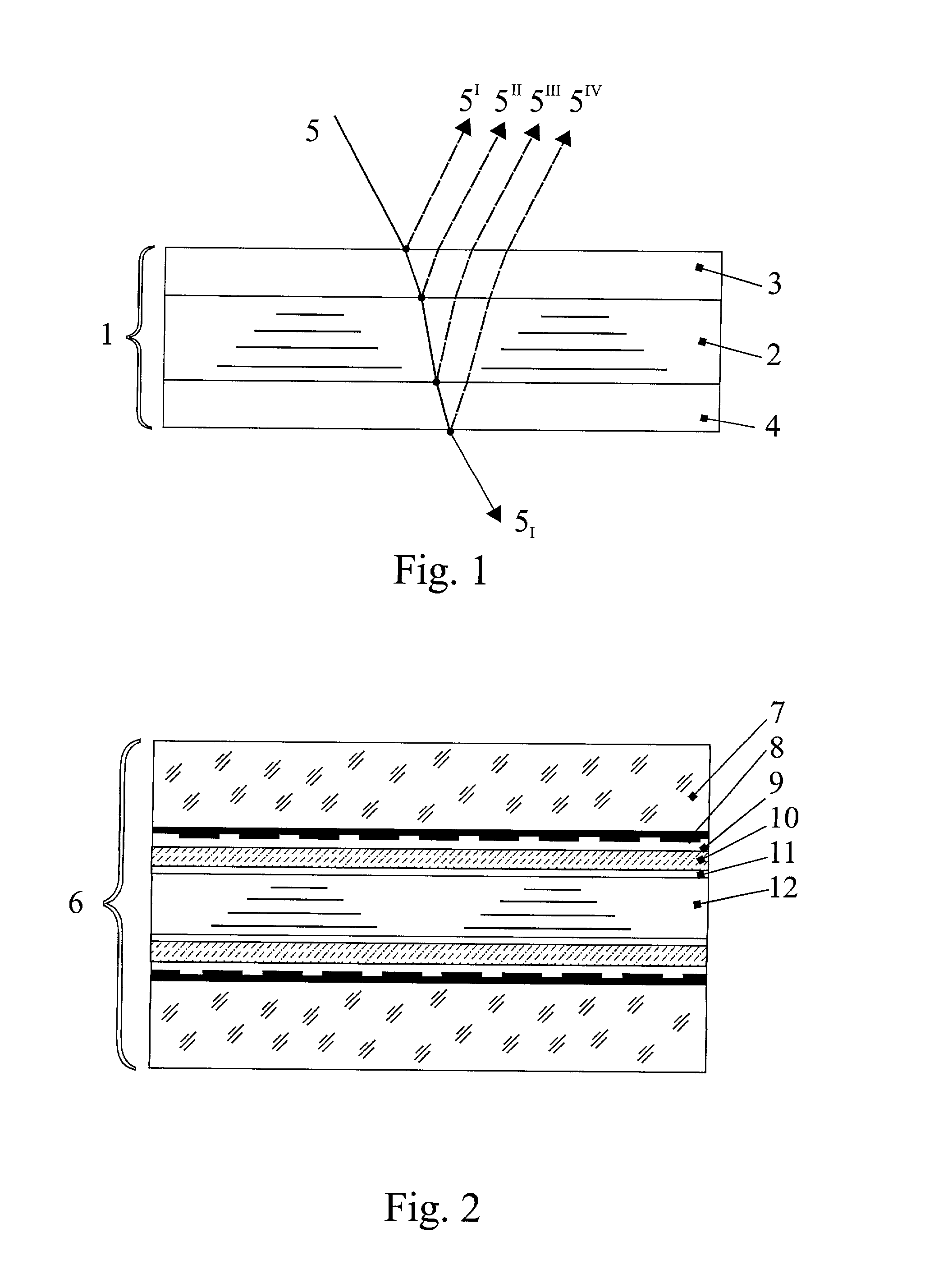
[0020] Let us consider, for example, a transmissive liquid crystal display. It consists of two plates, which can be made out of glass, plastic or other transparent material. On the internal surface of these plates facing the layer of nematic liquid crystal, one applies transparent electrodes. Over the transparent electrodes one applies polarizing films of polymer or other material, which smooth out the relief and give the entire surface of the plate uniform properties. Polarizing coatings are applied onto these films with their optical axes oriented mutually perpendicular. The polarizing coatings align the molecules of nematic liquid crystal. The plates and functional layers define panels on each side of the liquid crystal material.

[0021] For the purpose of color compensation in an liquid crystal display with super twist nematic (STN), one additionally introduces an optically anisotropic layer with a predetermined optical thickness situated on the second plate.

[0022] FIG. 2 is a cro...


PUM

PropertyMeasurementUnit
refractive indicesaaaaaaaaaa
thicknessaaaaaaaaaa
thicknessaaaaaaaaaa

Abstract

The invention pertains to information displays, in particular to liquid-crystal (LC) displays that can be used in indicatory devices of various types as well as in optical modulators, matrix systems of light indication, etc. The LC information display contains a layer of liquid crystal situated between the front and the rear panels with functional layers, and the liquid crystal has parameters providing interference maximum or minimum of transmission or reflection at the exit of the display and/or at the boundary of at least two functional layers and/or between the LC layer and a functional layer, for at least one linearly polarized component of light, and for at least one wavelength. The technical result of the declared invention is the enhancement of brightness and contrast of the image, especially for the light traveling normal to the surface of the display, decrease of thickness and simplification of the display design due to optimization of all or at least several functional layers and elements of the display and also due to incorporation of several functions in single layer, the decrease in losses and enhancement of optical characteristics of the display. Use of the declared invention allows optimizing transmission of light through optically anisotropic functional layers of the display, which leads to substantial increase of its effectiveness.

Description

[0001] This application claims priority to Russian Federation Application No. RU 2000130482 filed Dec. 6, 2000.[0002] 1. Field[0003] The invention pertains to information displays, in particular to liquid crystal displays, and can be used in the indication devices of various function, as well as in optical modulators, matrix systems of light indication, etc.[0004] 2. Description of the Related Art[0005] There are known liquid crystal information displays, implemented as a flat cell formed by two parallel glass plates, on the internal sides of which there are electrodes made out of optically transparent electrically conducting material, for example indium dioxide or tin oxide. The internal surface of the plates with electrodes undergoes a special processing to align the liquid crystal material. After assembling the cell, it is filled with liquid crystal, which forms a layer of 5-20 .mu.m, which constitutes the active medium which changes its optical properties (the angle of rotation ...

Claims


Application Information

Patent Timeline
Patent Type & Authority Applications(United States)
IPC IPC(8): G02F1/13G02F1/1335
CPCG02F1/133502Y10T428/10Y10T428/1041Y10T428/1036C09K2323/00C09K2323/03C09K2323/031G02F1/13363
Inventor LAZAREV, PAVEL I.
Owner NITTO DENKO CORP
Why Eureka
Try Eureka