Power plant with energy recovery from fuel storage

a technology of energy recovery and power plant, applied in the direction of fuel cell, steam engine plant, gas/liquid distribution and storage, etc., can solve the problems of serious technical and economic barriers, serious energy loss affecting the overall efficiency and economic viability, and gravely compromising the economic viability of hydrogen and natural gas as fuels for vehicular propulsion

Inactive Publication Date: 2002-08-22
QUSIR TECH
View PDF51 Cites 106 Cited by
  • Summary
  • Abstract
  • Description
  • Claims
  • Application Information

AI Technical Summary

Benefits of technology

0012] In such power plant systems, mechanical power and/or thermal energy may be recovered from the fuel storage systems. For example, a process is disclosed herein that involves providing

Problems solved by technology

Despite the great attractiveness of fueling future mobile and stationary power plants with hydrogen, severe technical and economic barriers are presented by the supply and storage of hydrogen (as either a compressed gas or a cryogenic liquid).
In the absence of any system for recovering energy as hydrogen fuel is released from storage, this energy loss seriously impairs the overall efficiency and economic viability of the so-called "hydrogen economy", as popularly represented by distributed fuel cell energy systems using hydrogen generated by renewable energy sources such as solar photovoltaic power.
In particular, the economic viability of hydrogen and natural gas as fuels particularly for vehicular propulsion has been gravely compromised by the loss of energy required to compress or liquefy these fuels in the fuel supply infrastructure.
There has been a lack of practical devices and methods for recovering hydrogen storage energy to enhance the performance and efficiency of

Method used


Image

  • Power plant with energy recovery from fuel storage
  • Power plant with energy recovery from fuel storage
  • Power plant with energy recovery from fuel storage

Examples


Embodiment Construction

[0026] Representative embodiments are described below with reference to the drawings. The following definitions are provided solely to aid the reader, and should not be construed to have a scope less than that understood by a person of ordinary skill in the art or as limiting the scope of the appended claims.

[0027] "Ambient pressure" denotes about 1.0 bar absolute with allowance for changes of elevation and barometric conditions.

[0028] "Ambient temperature" denotes about -40 to about 35.degree. C.

[0029] "Light gas or light product" denotes gas enriched in a less readily adsorbed component.

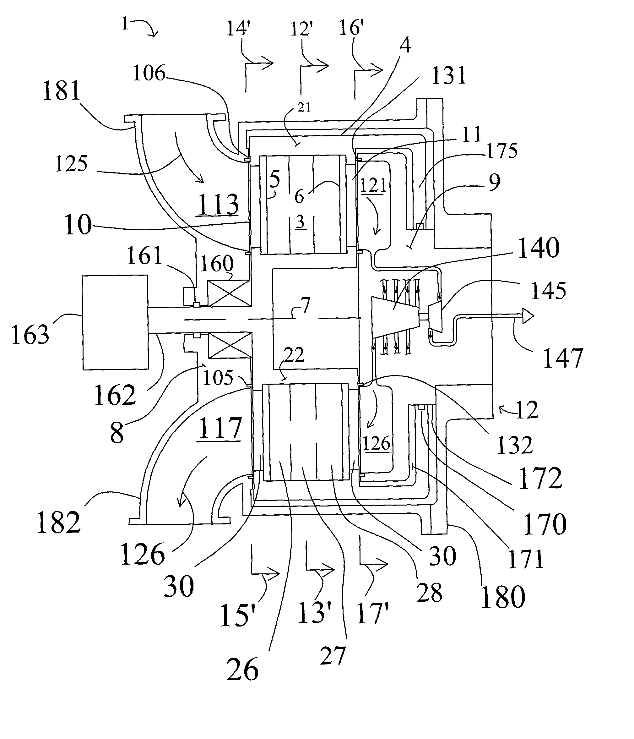
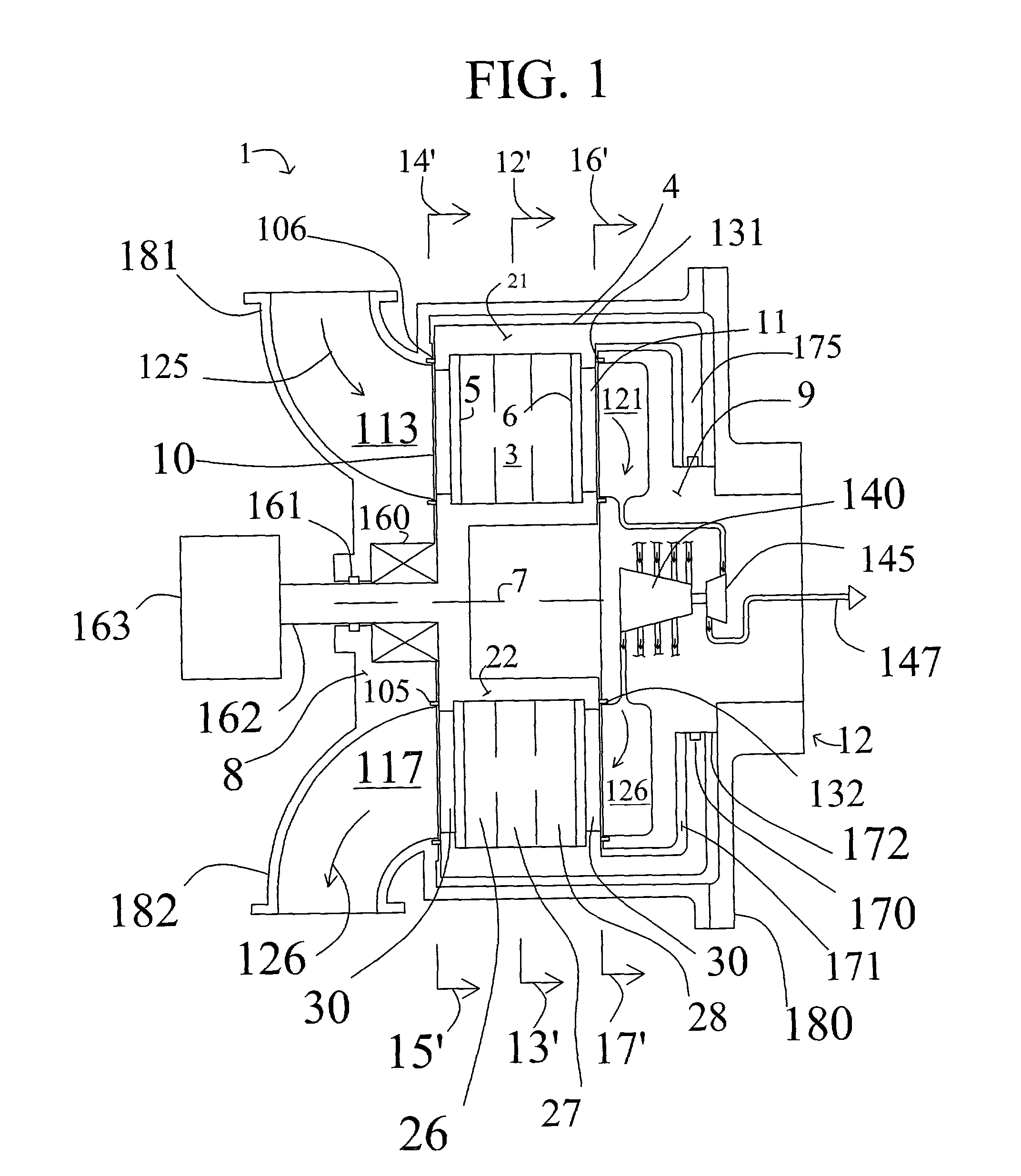
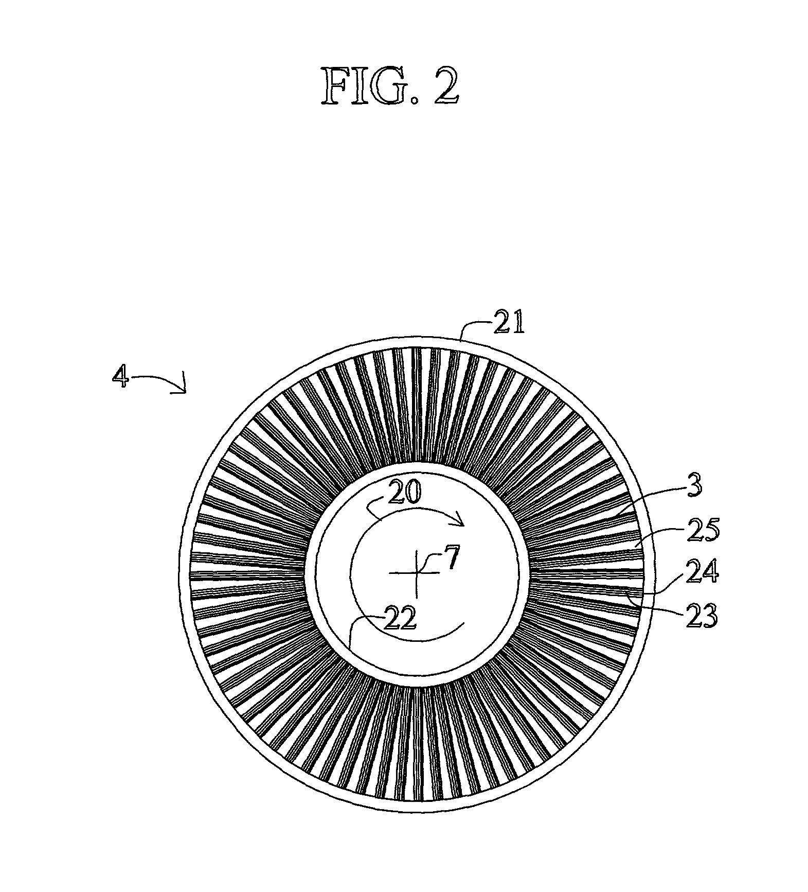
[0030] "Rotary bed pressure swing adsorption apparatus" is an adsorption apparatus where adsorbers with adsorbent material are rotated relative to stationary valves for introducing and withdrawing gas streams.

[0031] "Rotary valve pressure swing adsorption apparatus" is an apparatus where valves for introducing and withdrawing gas streams are rotated relative to stationary adsorbers housing adsorben...


PUM


Abstract

Power plant systems and processes are described that enable recovery of at least a portion of the fuel storage energy associated with a storage system for supplying fuel to the power plant systems. A first embodiment of an energy-recovery power plant system includes at least one fuel storage container and at least one expander that can receive fuel from the fuel storage container at a first pressure and provide the fuel to the power plant at a second pressure that is lower than the first pressure. A second embodiment of an energy-recovery power plant system includes a first conduit fluidly coupling the fuel storage container and the power plant for delivering fuel from the fuel storage container to the power plant and at least one regenerative thermodynamic cycle engine thermally coupled to the first conduit such that heat may be exchanged between the fuel and a working fluid for the regenerative thermodynamic cycle engine.

Description

CROSS REFERENCE TO RELATED APPLICATION[0001] The present application claims priority from prior pending U.S. provisional application No. 60 / 260,608, filed on Jan. 9, 2001, which is incorporated herein by reference.FIELD[0002] The present disclosure relates to a power plant system that includes a fuel storage system.BACKGROUND[0003] Fuel cells provide an environmentally friendly source of electrical power. One form of fuel cell used for generating electrical power, particularly for vehicle propulsion and for smaller scale stationary power generation, includes an anode channel for receiving a flow of hydrogen gas, a cathode channel for receiving a flow of oxygen gas, and a polymer electrolyte membrane (PEM) which separates the anode channel from the cathode channel. Oxygen gas entering the cathode reacts with hydrogen ions that cross the electrolyte to generate a flow of electrons. Environmentally safe water vapor is also produced as a byproduct.[0004] Despite the great attractiveness...

Claims


Application Information

Patent Timeline
IPC IPC(8): F02B43/10H01M8/04H01M8/06
CPCF02B43/10H01M8/04007H01M8/04089H01M8/04119F17C11/005Y02T10/16Y02T10/166Y02T10/32F02G1/043H01M8/0662Y02T10/12Y02T10/30Y02E60/50
Inventor KEEFER, BOWIE G.ROY, SURAJITST.-PIERRE, JEANNELSON, AMY E.KNIGHTS, SHANNA D.
Owner QUSIR TECH
Why Eureka
Try Eureka