Cooling system for electric vehicle

a technology for electric vehicles and cooling systems, applied in vehicle cooling devices, vehicle components, lighting and heating apparatuses, etc., can solve the problems of increasing the cost of fossil fuels, increasing the interest in electric vehicles, and heat generation, so as to improve the effectiveness of magnetic materials in the motor, reduce copper losses, and increase the power density

a technology for electric vehicles and cooling systems, applied in vehicle cooling devices, vehicle components, lighting and heating apparatuses, etc., can solve the problems of increasing the cost of fossil fuels, increasing the interest in electric vehicles, and heat generation, so as to improve the effectiveness of magnetic materials in the motor, reduce copper losses, and increase the power density

US20020112851A1Inactive Publication Date: 2002-08-22ODONNELL DENNIS W

Image

  • Cooling system for electric vehicle
  • Cooling system for electric vehicle
  • Cooling system for electric vehicle

Examples


Embodiment Construction

, particularly, when the detailed description is taken in conjunction with the attached drawing figures and with the appended claims.

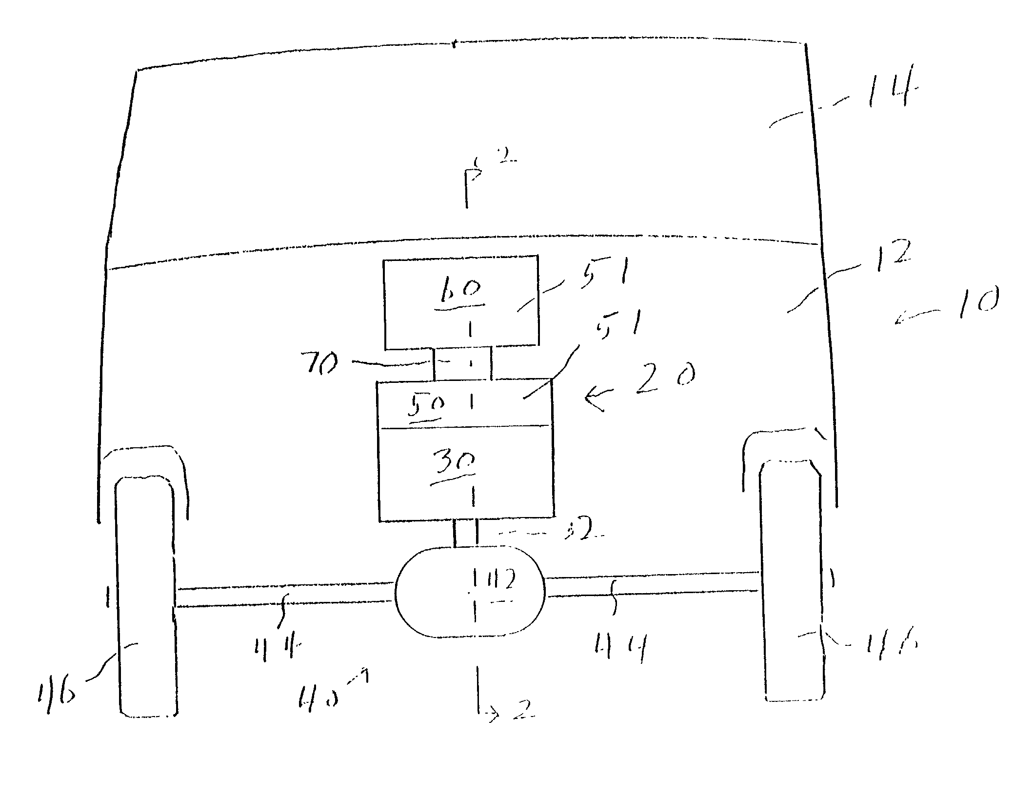
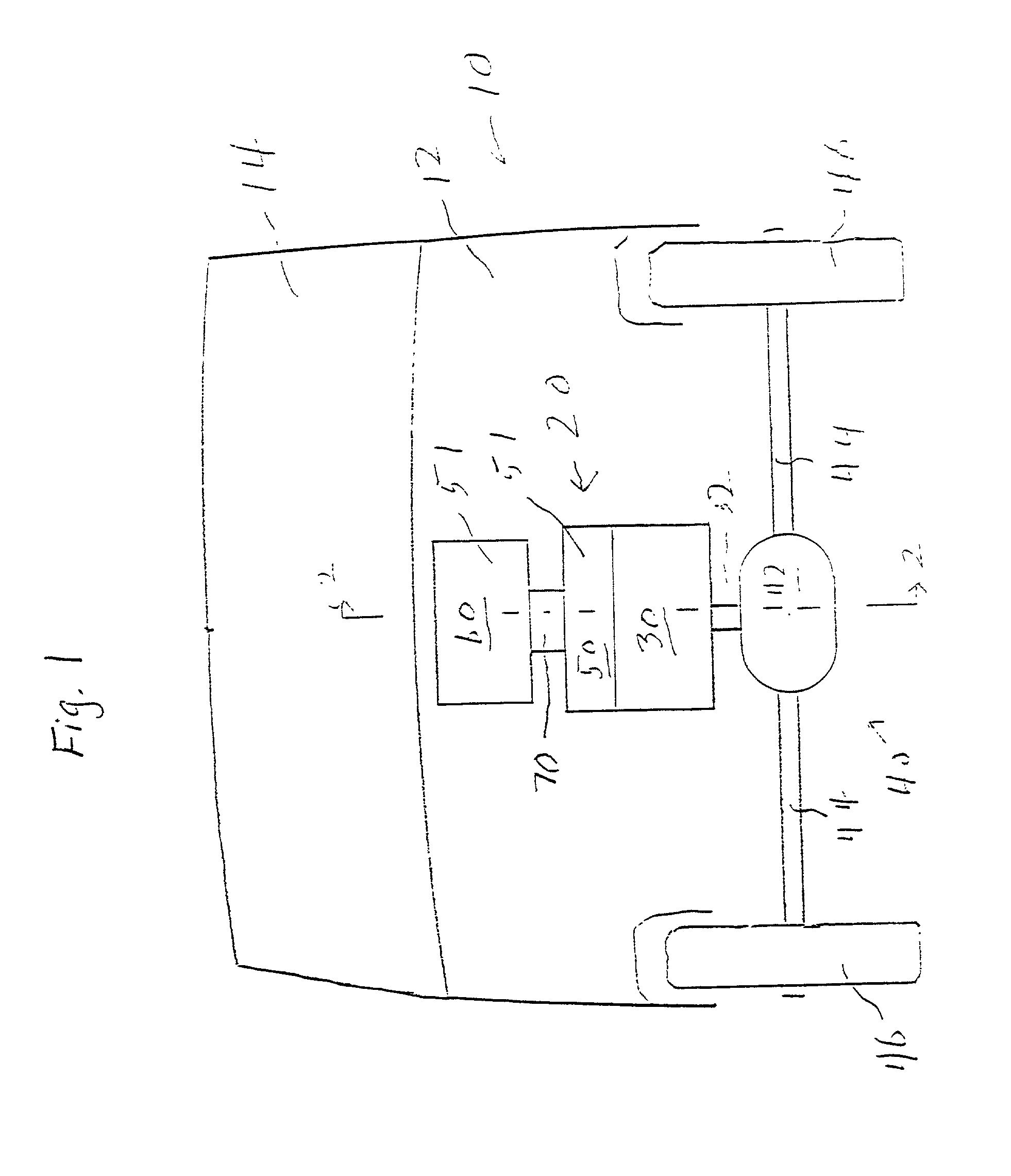
[0015] FIG. 1 is a schematic front view of a vehicle having a motive power system according to the present invention.

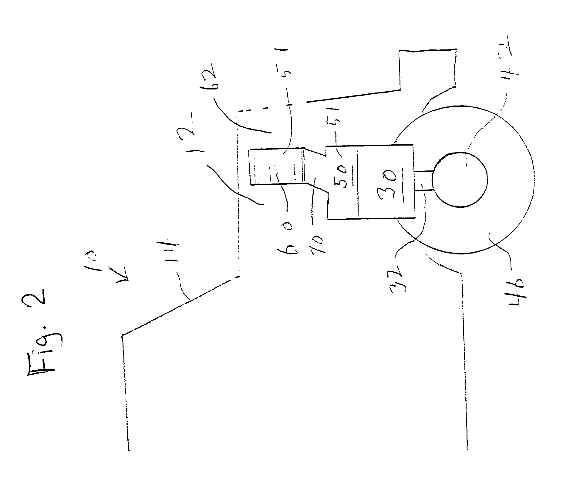
[0016] FIG. 2 is a schematic sectional view cut along the line 2-2 in FIG. 1.

[0017] FIG. 3 is a typical phase diagram of a coolant fluid.

[0018] FIG. 4 is a schematic illustration of a cooling system for an electric propulsion motor which employs a pair of fluid flow passages for conveying cooling fluid to and from a heat exchanger.

[0019] FIG. 5 is a schematic illustration of a cooling system including a fluid pump for conveying cooling fluid to a heat exchanger.

[0020] FIG. 6 is a schematic illustration of a cooling system which includes a compressor and an expansion valve to provide refrigeration of a motor in an electric vehicle.

[0021] FIG. 7 is a schematic illustration of a system having a capillary expansion valve for refrigerating a ...


PUM


Abstract

A motive power system for an electric vehicle has a drive train connected to one or more drive wheels of the vehicle. The motive power system has an electrical motor having a motive power output connection for attachment to the drive train. A first heat exchanger has thermal connection to the electrical motor to remove heat from the electrical motor, the first heat exchanger employing a coolant fluid. A second heat exchanger is in thermal contact with the coolant fluid and with an ambient atmosphere for removing heat from the coolant fluid.

Description

[0001] The present invention relates to cooling systems for electric vehicles.[0002] The increasing cost of fossil fuels has caused considerable interest in electric vehicles. These include battery powered vehicles, solar cell powered vehicles, and fuel cell powered vehicles. All such vehicles include one or more electric motors connected to drive wheels of the vehicles.[0003] Although electric motors generally have high efficiencies, heat generation does occur. Heat generation occurs due to conduction losses in the coils, hysteresis losses in the magnetic materials, as well as skin effect losses and eddy current losses in the coils and magnetic materials. Some heat is also generated by friction in the bearings and in brushes, if they are present.[0004] Prior art electric vehicles have generally been cooled by air, a circumstance which tends to limit the torque and power which can be obtained from the motors, and which permits temperature rise with an attendant loss of efficiency.[0...

Claims


Application Information

Patent Timeline
22 Aug 2002
Publication
US20020112851A1
IPC
B60H1/00; F28D15/02
CPC
B60H1/00392; F28D15/0266
Inventors
O'DONNELL, DENNIS W.