Side-looking NMR probe for oil well logging

a nmr probe and oil well technology, applied in the direction of nmr measurement, reradiation, instruments, etc., can solve the problems of nmr signal degradation, device operation at relatively low logging speed, limited axial extent of the examination region, etc., to improve the effectiveness of the tool, increase the effective radius, and the effect of greater depth

Inactive Publication Date: 2002-09-12
BAKER HUGHES INC
View PDF0 Cites 16 Cited by
  • Summary
  • Abstract
  • Description
  • Claims
  • Application Information

AI Technical Summary

Benefits of technology

0015] The present invention is a side-looking NMR probe for well logging applications. It incorporates a number of design features, some of which are novel in themselves, in a novel combination that greatly improves the effectiveness of the tool. The starting point is a configuration that includes a static field similar to that of a dipole, and a dipole-like RF field substantially orthogonal to the static field, with the centers of the equivalent static and RF dipoles laterally displaced to provide a match on a side defined as the front of the tool and a mismatch on the back of the tool. The basic static field may be produced by a main magnet. The static field in the region of investigation has a field strength within predetermined limits and a substantially uniform gradient. Those versed in the art would recognize that in a so-called zero gradient logging tool, in contrast, the static field in the region of investigation has a substantially uniform field strength around a saddle point. A second, shaping magnet is used to shape the static field to conform to the RF field over a larger azimuthal sector around the tool. The RF field is also shaped t

Problems solved by technology

With the Jackson arrangement, the axial extent of the region of examination is quite limited.
As a result of this, the device can only be operated at relatively low logging speeds: otherwise, because of the tool motion during logging, the magnitude of the static field changes significantly within a fixed region of the formation with an accompanying degradation of NMR signals.
Both of the Hanley devices suffer from the drawback that the axial extent of the region of examination is small, so that they cannot be operated at high logging speeds.
The effectiveness of the shield is limited by the diameter of the tool.
In the absence of a shield, the

Method used


Image

  • Side-looking NMR probe for oil well logging
  • Side-looking NMR probe for oil well logging
  • Side-looking NMR probe for oil well logging

Examples


Embodiment Construction

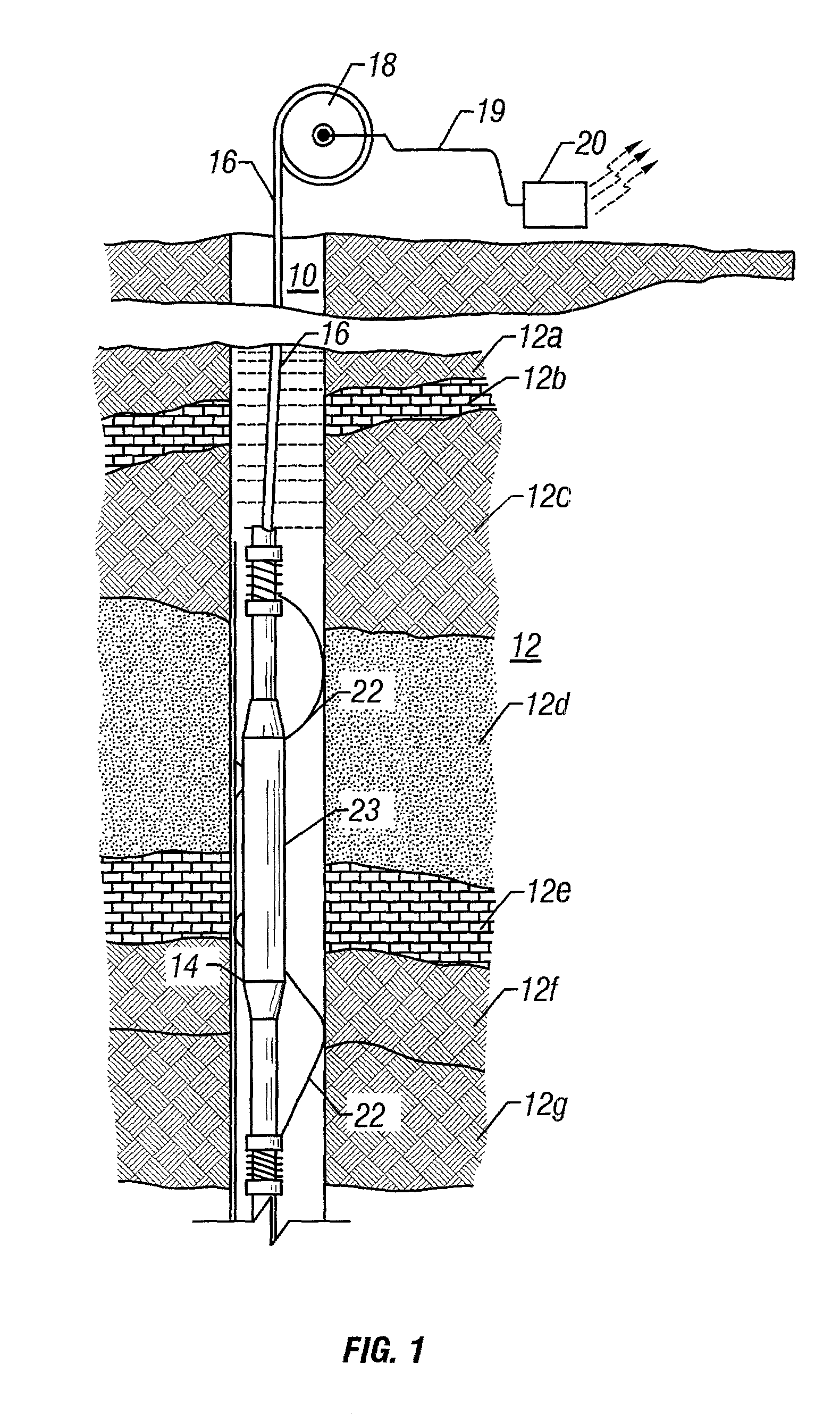
[0024] FIG. 1 depicts a borehole 10 which has been drilled in a typical fashion into a subsurface geological formation 12 to be investigated for potential hydrocarbon producing reservoirs. An NMR logging tool 14 has been lowered into the hole 10 by means of a cable 16 and appropriate surface equipment represented diagrammatically by a reel 18 and is being raised through the formation 12 comprising a plurality of layers 12a through 12g of differing composition, to log one or more of the formation characteristics. The NMR logging tool is provided with bow springs 22 to maintain the tool in an eccentric position within the borehole with one side of the tool in proximity to the borehole wall. The permanent magnets used for providing the static magnetic field is indicated by 23 and the magnet configuration is that of a line dipole. Signals generated by the tool 14 are passed to the surface through the cable 16 and from the cable 16 through another line 19 to appropriate surface equipment...


PUM


Abstract

A side-looking NMR logging tool incorporates a permanent magnet arrangement having a magnetization direction oriented towards a side of the tool and a dipole RE antenna displaced towards the front of the tool. The magnet arrangement produces a shaped region of investigation in front of the tool wherein the magnetic field has a uniform field strength and the RF field has a uniform field strength in a direction orthogonal to the static field. The shaping of the static field is accomplished by the magnet arrangement comprising a plurality of magnets having parallel magnetization or by a single shaped magnet. The antenna arrangement includes a gapped core made of non-ferritic soft material for increasing the antenna efficiency. The magnet arrangement also reduces ringing in the core and the antenna. An optional RF shield is used to reduce NMR signals from borehole fluids.

Description

CROSS REFERENCES TO RELATED APPLICATIONS[0001] This applications claims priority from U.S. Provisional Patent Application Ser. No. 60 / 221078 filed on Jul. 27, 2000.FIELD OF THE INVENTION[0002] This invention relates to apparatus and techniques for making nuclear magnetic resonance (NMR) measurements in boreholes, and to methods for determining magnetic characteristics of formations traversed by a borehole. Specifically, the invention relates to a side-looking NMR tool that attenuates NMR signals from the borehole while maintaining a large region of investigation within the formation.BACKGROUND OF THE INVENTION[0003] A variety of techniques have been used in determining the presence and in estimating quantities of hydrocarbons (oil and gas) in earth formations. These methods are designed to determine formation parameters, including among other things, porosity, fluid content, and permeability of the rock formation surrounding the wellbore drilled for recovering hydrocarbons. Typicall...

Claims


Application Information

Patent Timeline
IPC IPC(8): G01R33/44G01V3/32
CPCG01N24/081G01V3/32
Inventor REIDERMAN, ARCADYBEARD, DAVID R.
Owner BAKER HUGHES INC
Why Eureka
Try Eureka