Production method and device for hologram

a production method and hologram technology, applied in the field of holograms, can solve the problem of no report on the development of the two-beam exposure apparatus, and achieve the effect of improving the interference between the two beams

Inactive Publication Date: 2002-09-12
JAPAN SCI & TECH CORP
View PDF0 Cites 42 Cited by
  • Summary
  • Abstract
  • Description
  • Claims
  • Application Information

AI Technical Summary

Benefits of technology

0034] The apparatus on the present invention employs a mirror optical component in terms of using the minimum number of transparent optical component. This allows any degradation of the coherence of the two beams to b

Problems solved by technology

Heretofore, no report on a development of the two-beam exposure apparatus has been made, partially because it has been not clea

Method used


Image

  • Production method and device for hologram
  • Production method and device for hologram
  • Production method and device for hologram

Examples


example

Example 1

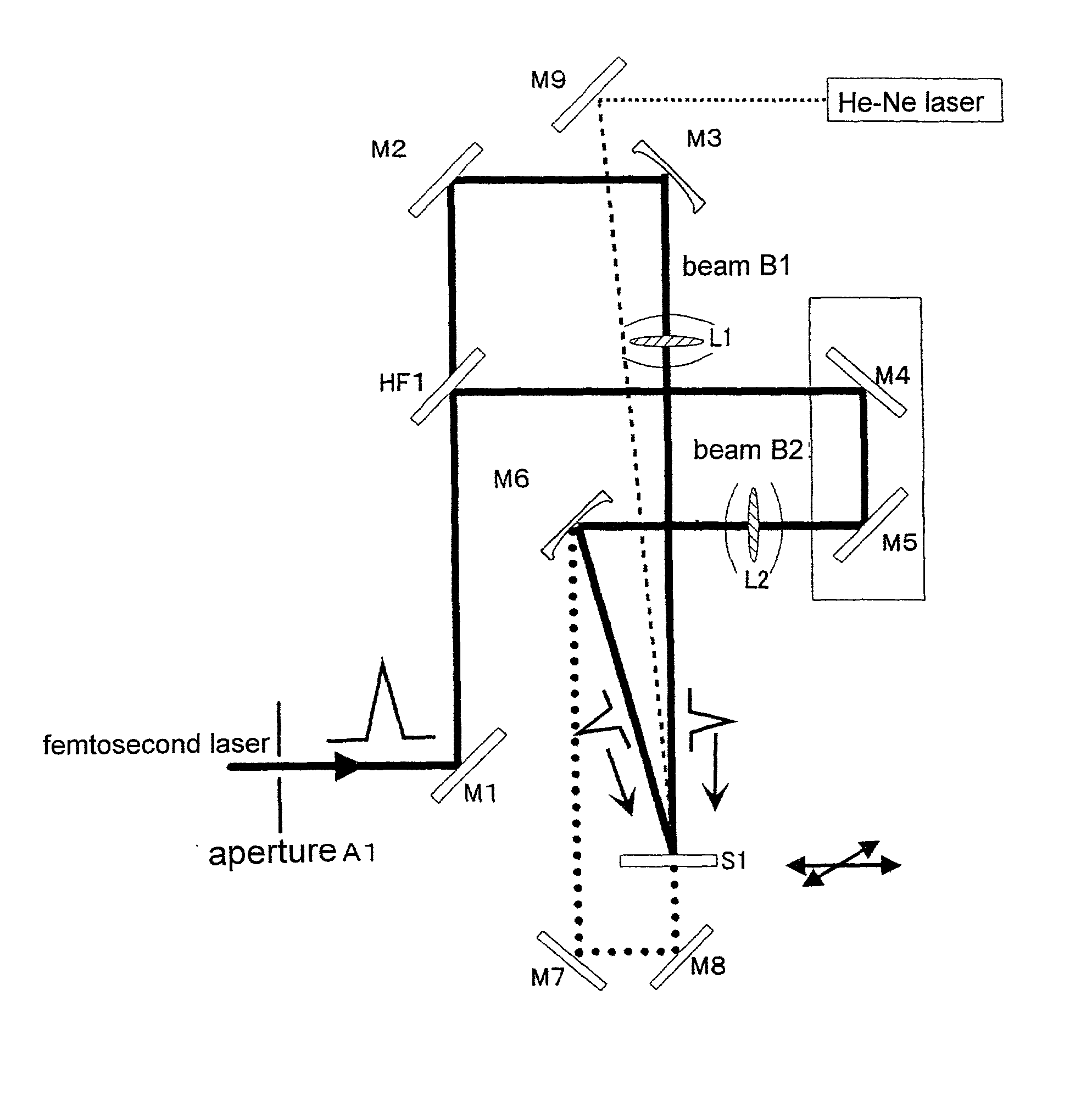
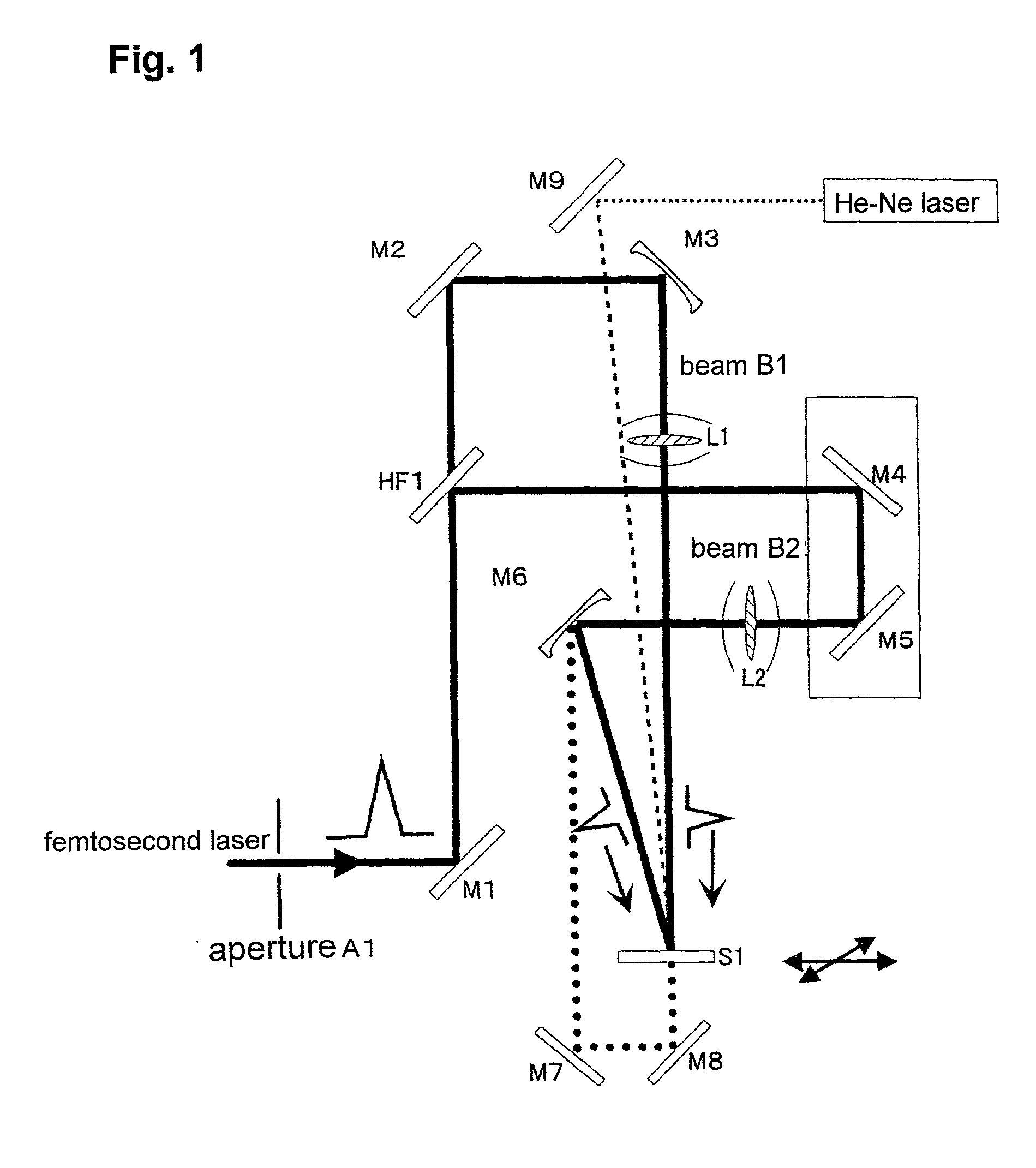
[0056] Using the two-beam laser interference exposure optical system, a transmission type hologram was recorded in ambient air. A combination of the plane mirror M3' and lens L1 and a combination of the plane mirror M6' and lens L2 were used. A single crystal of sapphire (10.times.10.times.1 mm) was used as the substrate S1 for recording a hologram therein. A laser beam was entered perpendicular to the "c plane" of the sapphire single crystal. The pulse energies of the beam B1 and beam B2 were arranged in 0.7 mJ and 0.3 mJ, respectively, and thus the laser output was about 1 mj / pulse. Using a singe pulse, a hologram was recorded by converging each of the beams with a spot size of about 10 .mu.m diameter. Further, in order to bring the laser beam into a Gaussian distribution through a shaping process, an aperture control element A1 was inserted in the optical path. As a result, the energy of the beams B1 and B2 necessary for recording a hologram could be reduced by 20%.

[0057...

example 2

[0059] Using the same two-beam laser interference exposure optical system as that of Example 1, a surface relief type hologram was recorded in a metallic film. In order to bring the laser beam into a Gaussian distribution through a shaping process, an aperture control element A1 was inserted in the optical path. A metallic film formed on a glass through a vacuum deposition process and having a thickness of about 250 nm was used as the substrate for recording a hologram therein. After the shaping process, the pulse energies of the beams B1 and B2 were 0.13 mj and 0.07 mj, respectively. The angle .theta. between the two beams was 20 degrees. The fringe distance of the obtained diffraction grating could correspond to a value derived from the following formula by using a laser wavelength .lambda.=800 nm and an air which gives n=1;

.lambda.=n.multidot.d.multidot.sin .theta. / 2

example 3

[0060] Using the same two-beam laser interference exposure optical system as that of Example 1, a surface relief type hologram was recorded in a silica film. A SiO.sub.2 thin film (film thickness: 114 nm) formed on a Si single crystal through a thermal oxidization was used as the substrate. The energy intensity of each of the beams B1 and B2 was 25 .mu.j, and the beams B1 and B2 were converged with a diameter of about 100 .mu.m on the surface. The angle between the two beams was 90 degrees, and a calculated fringe distance of the obtained diffraction grating was 580 nm.

[0061] FIG. 7 shows an AFM image of the obtained diffraction grating. From this AFM image, it could be confirmed that a surface relief type hologram having a groove depth of 2 to 3 nm and a groove distance of 580 nm was formed. The groove depth was 2 to 3% of the film thickness of the silica glass, and this value could correspond to a shrinkage percentage in connection with an optically induced structural change in th...


PUM


Abstract

A method and apparatus for producing a hologram using a two-beam laser interference exposure process, comprising the steps of using as a light source a femtosecond laser having a pulse width of 900-10 femtoseconds and a peak output of 1 GW or more and capable of generating a pulse beam at or close to the Fourier transform limit, dividing the pulse beam from the laser into two by a beam splitter, controlling the two beams temporally through an optical delay circuit and spatially using plane and concave mirrors each having a slightly rotatable reflection surface to converge the beams on a surface of or within a substrate for recording a hologram at an energy density of 100 GW/cm.sup.2 or more with keeping each polarization plane of the two beams in parallel so as to match the converged spot of the two beams temporally and spatially, whereby a hologram is recorded irreversibly on the substrate formed of a transparent material, semiconductor material or metallic material.

Description

TECHNICAL FIELD[0001] The present invention relates to the technology of holograms, and more particularly to a method and apparatus for efficiently producing a hologram having excellent embedability with a microscopic surface area and thickness thereof, high diffraction efficiency and therefore enhanced applicability to various recording substrates. The present invention also relates to a product incorporating such a hologram.BACKGROUND ART[0002] High energy density no fewer than 1 TW (10.sup.12W)cm.sup.3 may be obtained by a femtosecond laser. When a light having such a high energy density is irradiated onto a material, high-density electrons will be excited in a short time period in the irradiated material. The energy of the excited electrons is converted into the vibrational energy of ions in the material within one nanosecond. Once the vibration energy density exceeds a given threshold, the ions break away from the material, resulting in an abrasion of the material. The abrasion...

Claims


Application Information

Patent Timeline
IPC IPC(8): G02B5/32G02B6/12G02B5/18G03H1/04H01S3/00H01S5/125
CPCG02B2006/12107G03H1/0272G03H1/04G03H2001/0482G03H2222/33G03H2260/62G03H2270/11G03H2270/13H01S3/0057
Inventor HOSONO, HIDEOHIRANO, MASAHIROSARUKURA, NOBUHIKOKAWAMURA, KENICHI
Owner JAPAN SCI & TECH CORP
Why Eureka
Try Eureka