
Time-tracking for clustered demodulation elements in a spread spectrum system

a spread spectrum and time tracking technology, applied in the field of demodulating spread spectrum signals, to achieve the effects of improving signal to noise ratio, power control and capacity, and improving performance in unresolvable multipath environments

Inactive Publication Date: 2002-09-12
QUALCOMM INC
View PDF7 Cites 5 Cited by
  • Summary
  • Abstract
  • Description
  • Claims
  • Application Information

AI Technical Summary

Benefits of technology

[0011] The receiver includes merge protection that prevents clustered demodulation elements from converging to less than a threshold time separation. Time-tracking commands that would otherwise cause demodulation elements to have a time separation below the threshold are intercepted and filtered. In this manner, the merge protection time-tracking feature allows clusters of demodulation elements to track one or more paths in unresolvable multipath environments without merging and being deassigned. Among other advantages, merge protection prevents the demodulation elements from contracting below a minimum time span. By ensuring a minimum time span, merge protection allows the demodulation elements to adaptively adjust and maintain a total time span so as to contain substantially all of the energy of the received spread spectrum signal.
[0013] These features may be selectively enabled for independent use, or may be used in conjunction to further improve performance. Consequently, the receiver can achieve significant improvements in unresolvable multipath environments, including improved signal to noise ratio, power control and capacity. The techniques may be advantageous in multipath environments in which multiple paths exist but have a small time separation such that the individual signal peaks are not readily detectable, such as a time separation of less than 1.5-2.0 chips. Furthermore, the techniques may be particularly advantageous for environments in which the time separation is between, for example, 0.25 chips and 2.0 chips.

Problems solved by technology

For shorter time separations, often referred to as "unresolvable multipath spacing," conventional receivers typically do not assign multiple demodulation elements because the multiple paths often appear as a single mass of energy without readily detectable peaks.

Method used


Image

  • Time-tracking for clustered demodulation elements in a spread spectrum system
  • Time-tracking for clustered demodulation elements in a spread spectrum system
  • Time-tracking for clustered demodulation elements in a spread spectrum system

Examples


Embodiment Construction

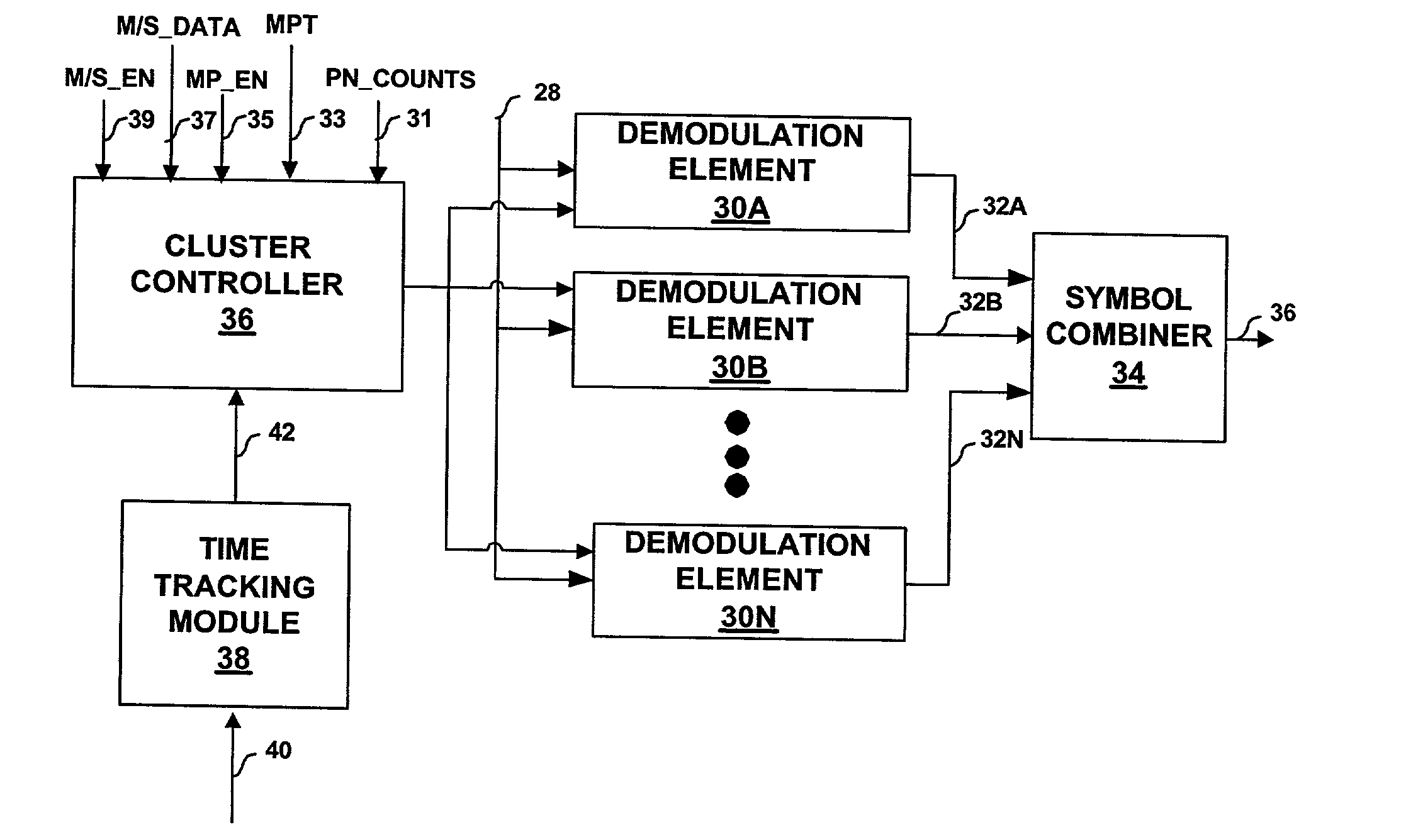
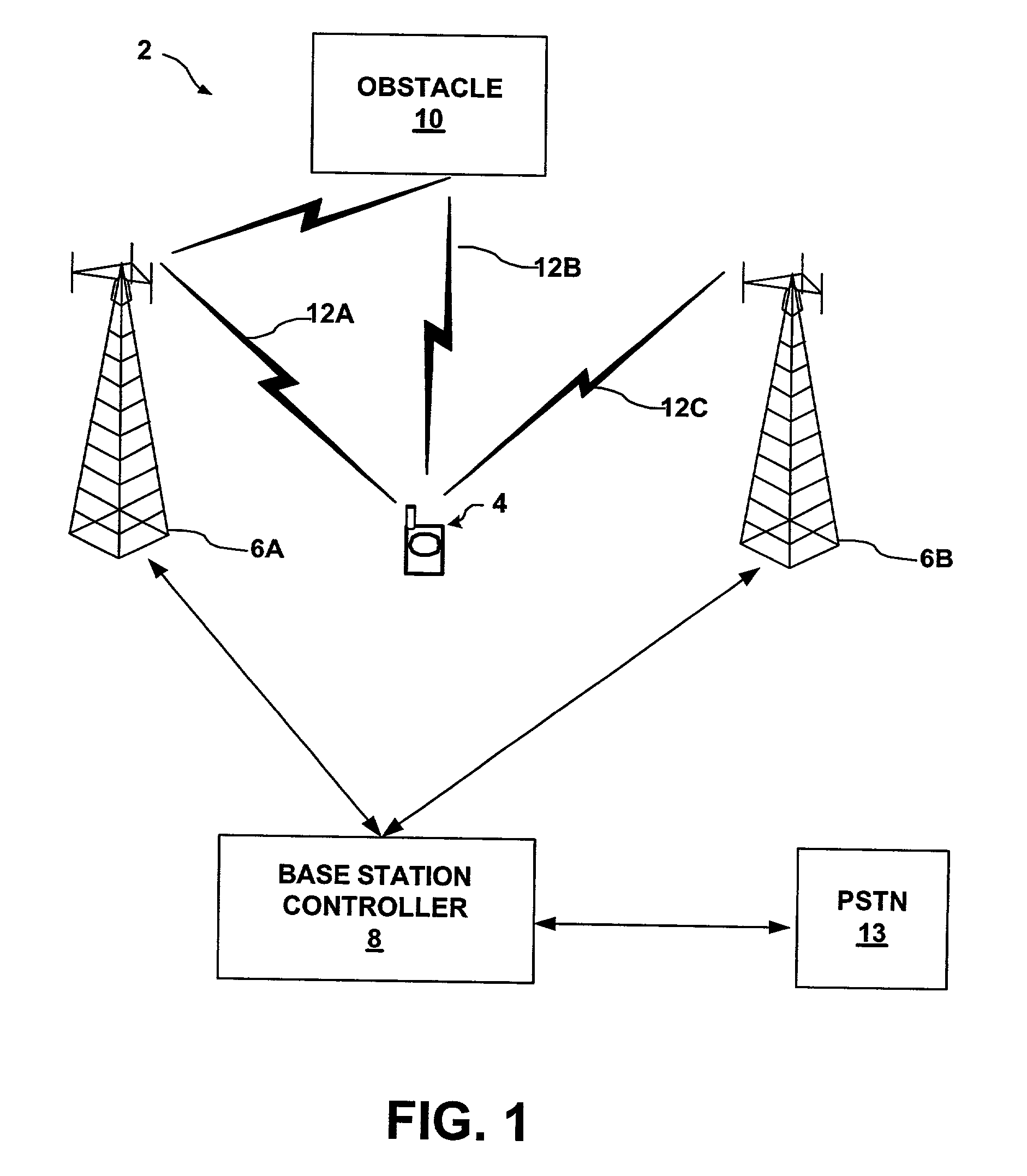
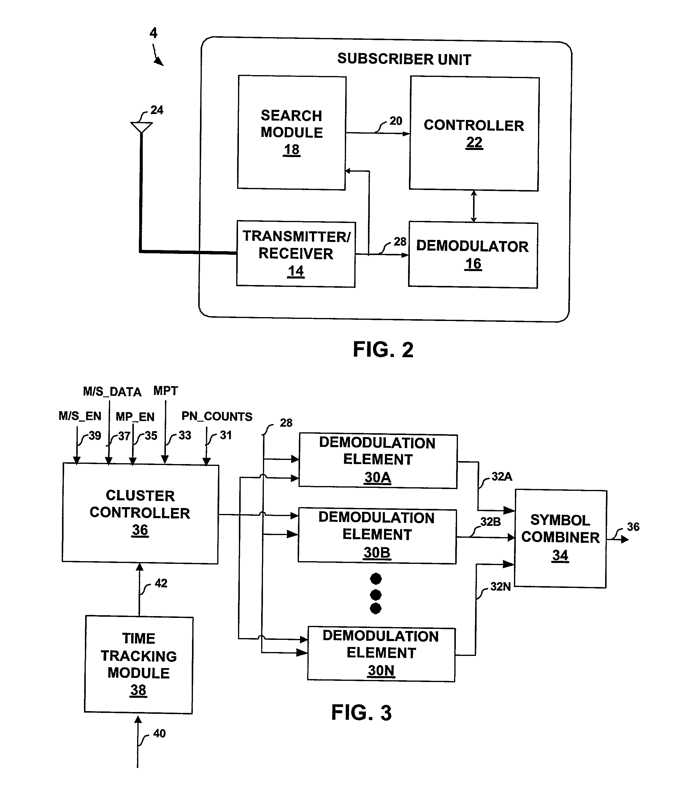
[0032] FIG. 1 is a block diagram illustrating a spread spectrum telecommunication system 2 in which subscriber unit 4 receives a number of spread spectrum signals 12, also referred to herein as "paths." In particular, subscriber unit 4 receives signal 12A from base station 6A, as well as signal 12B caused by reflection of signal 12A from obstacle 10. In addition, subscriber unit 4 receives a spread spectrum signal 12C from base station 6B. Obstacle 10 may be any structure proximate subscriber unit 4 such as a building, bridge, car or even a person. Examples of subscriber unit 4 include a cellular radiotelephone, a satellite radiotelephone, a PCMCIA card incorporated within a computer, a personal digital assistant (PDA) equipped with wireless communication capabilities, and the like. Base station controller (BSC) 8 provides an interface between base stations 6 and the public switched telephone network (PSTN) 13. In this manner, BSC 8 may route calls between subscriber units 4 and oth...


PUM


Abstract

An apparatus, such as a subscriber unit or a base station within a spread spectrum communication system, provides advanced control over the time-tracking of demodulation elements when unresolvable multipath situations arise. The apparatus provides merge protection that prevents clustered demodulation elements from contracting beyond a minimum time span. In addition, the apparatus provides a master / slave feature for synchronizing the time-tracking of the demodulation elements when clustered around a multipath signal.

Description

RELATED APPLICATIONS[0001] This application claims priority from U.S. Provisional Application Serial No. 60 / 261,402, entitled "SYSTEM STUDY: RECEIVER STRUCTURES IN FADING CHANNELS WITH NON-NEGLIGIBLE MULTIPATH SPACING: THE "FAT-PATH" CONCEPT," filed Jan. 11, 2001, the content of which is incorporated herein by reference in its entirety.TECHNICAL FIELD[0002] The invention relates generally to wireless communication systems and, more particularly, to demodulating spread spectrum signals.BACKGROUND[0003] A number of conventional wireless communication techniques have been developed. One common technique is code division multiple access (CDMA) in which multiple communications are simultaneously conducted over a radio-frequency (RF) spectrum. Example wireless communication devices ("subscriber units") that have incorporated CDMA technology include cellular radiotelephones, satellite radiotelephones, PCMCIA cards for portable computers, personal digital assistants (PDAs) equipped with wir...

Claims


Application Information

Patent Timeline
Patent Type & Authority Applications(United States)
IPC IPC(8): H04B7/06H04B1/7117
CPCH04B1/7085H04B1/7117H04B7/0697
Inventor RICK, ROLAND R.PATEL, SHIMMANSAINTS, KEITHZHANG, HAITAO
Owner QUALCOMM INC
Learn More