Cutting tool

a cutting tool and cutting tool technology, applied in the field of cutting tools, can solve the problems of reducing affecting the cutting tool, and affecting the cutting tool, and achieve the effect of optimizing the width of the chamfer

Inactive Publication Date: 2002-09-12
NGK SPARK PLUG CO LTD
View PDF0 Cites 32 Cited by
  • Summary
  • Abstract
  • Description
  • Claims
  • Application Information

AI Technical Summary

Benefits of technology

[0006] It is accordingly an object of the present invention to provide a cutting tool used with a depth of cut that causes only a curved cutting edge or a portion thereof to be used for cutting, which can attain an elongated life without incurring a decrease in the surface roughness.
[0008] With the cutting tool structured as above, it becomes possible to obtain such a width of chamfer that can be varied in proportion to the thickness of chip that in turn varies depending upon a variation of the depth of cut and the feed, thus making it possible to obtain an optimal width of chamfer at each place of cut. Namely, in finish cutting by turning, the depth of cut is selected so that the cutting is performed by a portion of the cutting tool that is located within the curved cutting edge at the nose. By the cutting tool structured as above, it becomes possible to perform cutting by positioning a circular or curved cutting edge portion smaller in the width of the chamfer on the front relief terminal side and a curved cutting edge portion larger in the width of the chamfer on the side relief terminal side, thus making it possible to elongate the life of the cutting tool without incurring a decrease in the surface roughness. In the meantime, while the width of the chamfer decreases gradually from the midpoint of the curved cutting edge to the junction of the curved cutting edge and each of the straight cutting edges, a decrease in the strength of the cutting edge is not actually caused since the depth of cut at finish cutting is mostly 1 / 2 of the nose radius.
[0010] As described above, the width of the chamfer of the cutting tool according to the first aspect of the present invention increases toward the middle point of the curved cutting edge so that the difference in the direction of feed does not cause any difference in the effect of the cutting tool. In contrast to this, the cutting tool according to the second aspect of the present invention produces different effects depending upon the direction of feed. However, since the chamfer of the cutting tool according to the second aspect of the present invention can have an increasing width in accordance with an increase of the thickness of the chip since the width of the chamfer of the cutting tool is adapted to increase gradually from one straight cutting edge to the other straight cutting edge, thus making it possible to obtain an optimal width of chamfer at each place of cut.
[0012] With the cutting tool having the wiper edges between the curved cutting edge and the respective straight cutting edges, the roughness (surface quality) of the finished surface can be improved when finish cutting is carried out by using the wiper edge. On the other hand, since a large thrust force results from the cutting by using the wiper edge, it is necessary to make basically smaller the width of the chamfer. However, when the width is made smaller throughout the entirety of the chamfer, the width of the chamfer becomes insufficient at the side relief terminal portion so that breakage of the cutting tool is liable to occur. In this connection, with a varying with of chamfer, the surface roughness can be improved without lowering the strength.
[0014] The cutting tool according to the third aspect of the present invention can produce the same effect irrespective of the direction of feed. In contrast to this, the cutting tool according to the fourth aspect of the present invention produces different effects depending upon the direction of feed. However, the cutting tool according to the fourth aspect of the present invention makes it possible to obtain an optimal width of chamfer at each place of cut.

Problems solved by technology

In case finish cutting is done with such a prior art cutting tool, i.e., a tool having a uniform chamfer along the cutting edge, there occurs the following problems.
Such a cutting tool does not have at the side relief terminal portion a chamfer of the width corresponding to the thickness of the chip, thus causing a problem that chipping or breakage of the cutting tool is liable to occur.
Although finish cutting is done by the curved cutting edge at the nose, the depth of cut varies at all times. Thus, if the width of the chamfer is constant, an increase in the depth of cut at or adjacent the side relief terminal portion causes a relative decrease in the width of chamfer thereat, thus causing a decrease in the strength.
On the other hand, if the depth h of cut is decreased too much, the width of the chamfer at a cutting edge portion adjacent the front relief terminal portion becomes too large, thus deteriorating the roughness of the finished surface.
Thus, the width of chamfer of the cutting edge along the nose varies so largely, thus causing a problem that the roughness of the finished surface is deteriorated.

Method used


Image

  • Cutting tool
  • Cutting tool
  • Cutting tool

Examples


Embodiment Construction

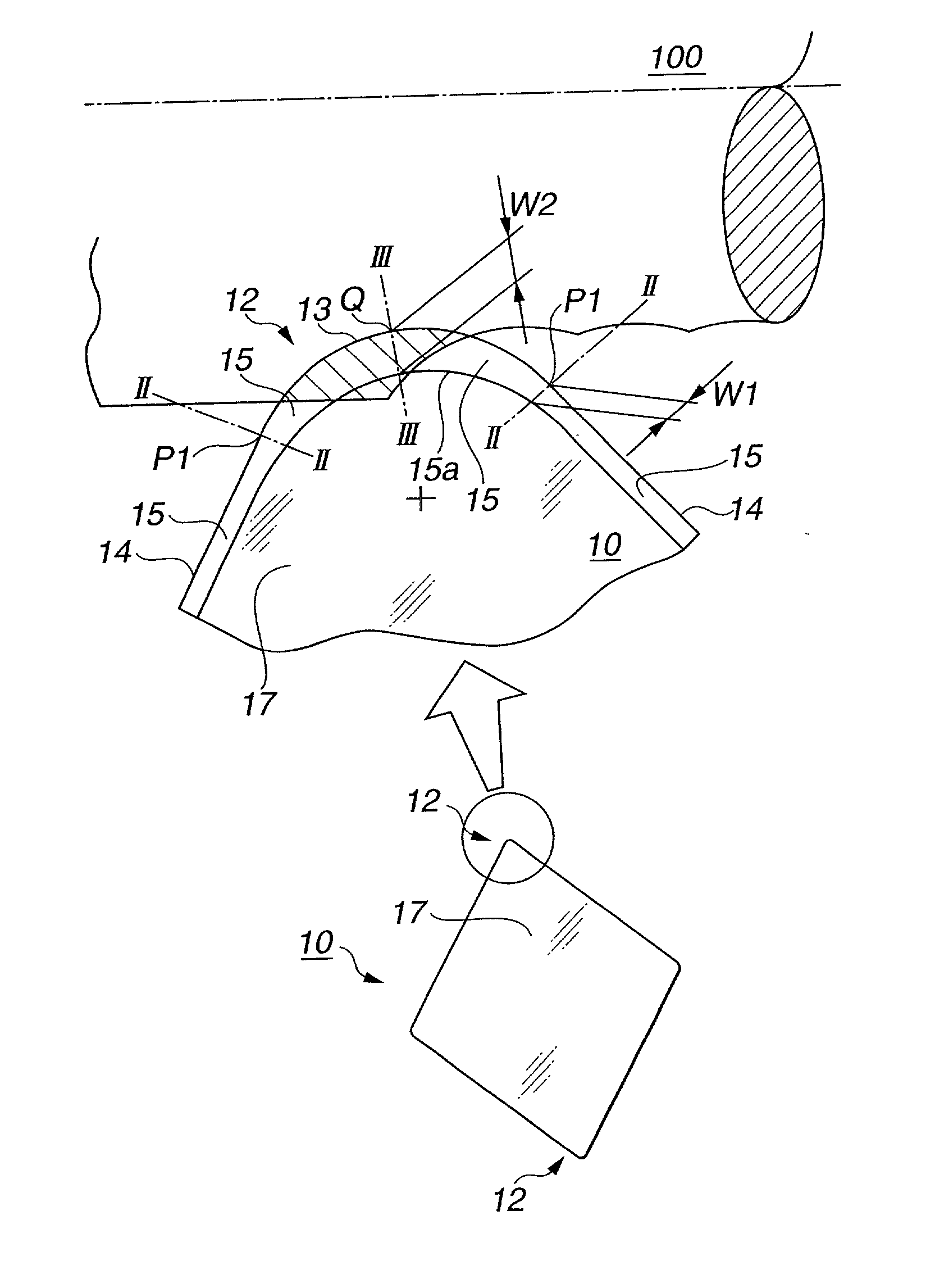
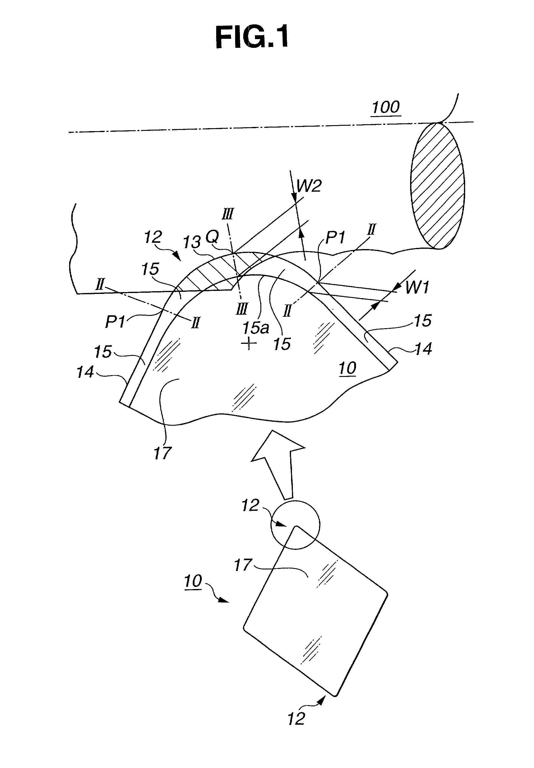
[0029] Referring first to FIGS. 1 to 3, a cutting tool according to an embodiment of the present invention is generally designated by 10 and adapted to constitute a rhombic indexable insert. The cutting tool 10 is constituted according CNGA120412 specified in ISO (i.e., rhombic insert of negative rake type with a cylindrical fixing hole, apex angle of 80 degrees and nose radius of 1.2 mm) and made of ceramic (Al.sub.2O.sub.3).

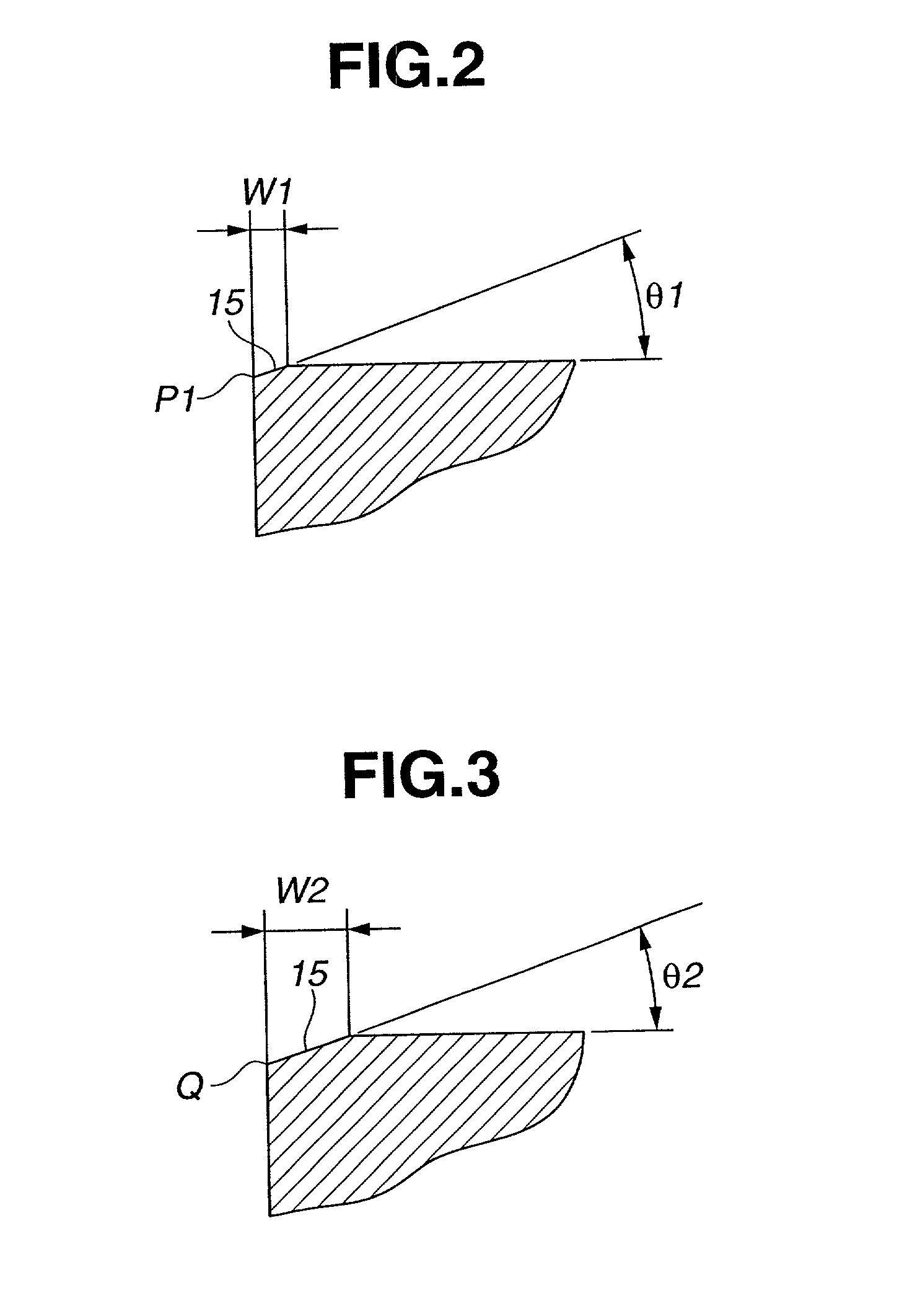
[0030] The cutting tool 10, as shown in FIG. 1, has a circular or curved cutting edge 13 at a nose 12 and a pair of straight cutting edges 14, 14 between which the nose 12 is located. The cutting tool 10 further has a chamfer 15 extending along the curved cutting edge 13 and the straight cutting edges 14, 14. The chamfer 15 is shaped so as to have a minimum width W1 (0.05 mm) at a junction P1 (the place indicated by line II-II) of the curved cutting edge 13 and each of the straight cutting edges 14 and a maximum width W2 at a midpoint Q of the curved cutting ed...


PUM

PropertyMeasurementUnit
widthaaaaaaaaaa
widthaaaaaaaaaa
radiusaaaaaaaaaa

Abstract

A cutting tool is provided which comprises a curved cutting edge at a nose, a pair of straight cutting edges between which the nose is located, and a chamfer extending along the curved cutting edge and the straight cutting edges so as to form a curved ridge at a junction of a portion of the chamfer extending along the curved cutting edge and a tool face. A portion of the chamfer increases in width from a junction of the curved cutting edge and each of the straight cutting edges to a midpoint of the curved cutting edge when observed in plan.

Description

BACKGROUND OF THE INVENTION[0001] The present invention relates in general to cutting tools for metal cutting and particularly to indexable inserts (throwaway tips) used for finish cutting by turning.[0002] FIG. 10 shows a positional relation between a cutting tool (hereinafter will be also referred to as indexable insert or simply as insert) 1 used for finish cutting or machining of a material having a large hardness and a work 100 to be finished thereby when observed from the tool face 7 side. By the hatched part is indicated the cross sectional shape of a chip. The indexable insert 1 has at a nose 2 thereof a circular or curved cutting edge 3 when observed in plan. The indexable insert 1 used in this kind of finish cutting is generally used at a relatively small depth h of cut which is equal to or smaller than 1 / 2 of the nose radius (i.e., the radius of the curved cutting edge 3 at the nose 2). Accordingly, the chip usually becomes thinnest at a portion which is cut by a cutting ...

Claims


Application Information

Patent Timeline
Patent Type & Authority Applications(United States)
IPC IPC(8): B23B5/12B23B27/00B23B27/14
CPCB23B27/145B23B2200/201B23B2200/283B23B2200/3654Y10T407/235Y10T407/23B23B5/12
Inventor KINUKAWA, TATSUJIKOIDE, MINORU
Owner NGK SPARK PLUG CO LTD
Why Eureka
Try Eureka