Hydrostatic transaxle having axial piston motor and method for manufacturing transaxles

a technology of axial piston motor and hydrostatic transaxle, which is applied in the direction of fluid gearing, transportation and packaging, gearing, etc., can solve the problems of difficult center section machining, noisy integrated hydrostatic transaxles, and high cos

Inactive Publication Date: 2002-09-12
HUSQVARNA AB
View PDF0 Cites 5 Cited by
  • Summary
  • Abstract
  • Description
  • Claims
  • Application Information

AI Technical Summary

Benefits of technology

0019] A further improvement in the transaxle of the present invention is the use of a brake cover, which may be made of molded plastic, in order to protect the brake disc from debris.

Problems solved by technology

Although utilizing a single casing for both the transmission and axle gear components necessitates only two large die castings, there are certain disadvantages inherent in such a design.
One such disadvantage is that servicing of the hydrostatic transmission or the gear train / differential requires that the entire casing be opened, the oil drained and the complete mechanism withdrawn in order to perform such service.
Since such casings are quite large and require expensive tooling to manufacture, this represents a significant additional cost.
Furthermore, integrated hydrostatic transaxles are often noisy, especially when accelerating.
Center section machining is difficult because the center section is substantial in size and machined surfaces are substantially perpendicular, often requiring multiaxis machining capabilities.
This corresponds to a significant cost associated with this design type.
Arranging the fixed swash plate and pump and motor mechanism, in the manner described above, poses a significant step in the assembly process which represents additional cost.

Method used


Image

  • Hydrostatic transaxle having axial piston motor and method for manufacturing transaxles
  • Hydrostatic transaxle having axial piston motor and method for manufacturing transaxles
  • Hydrostatic transaxle having axial piston motor and method for manufacturing transaxles

Examples


Embodiment Construction

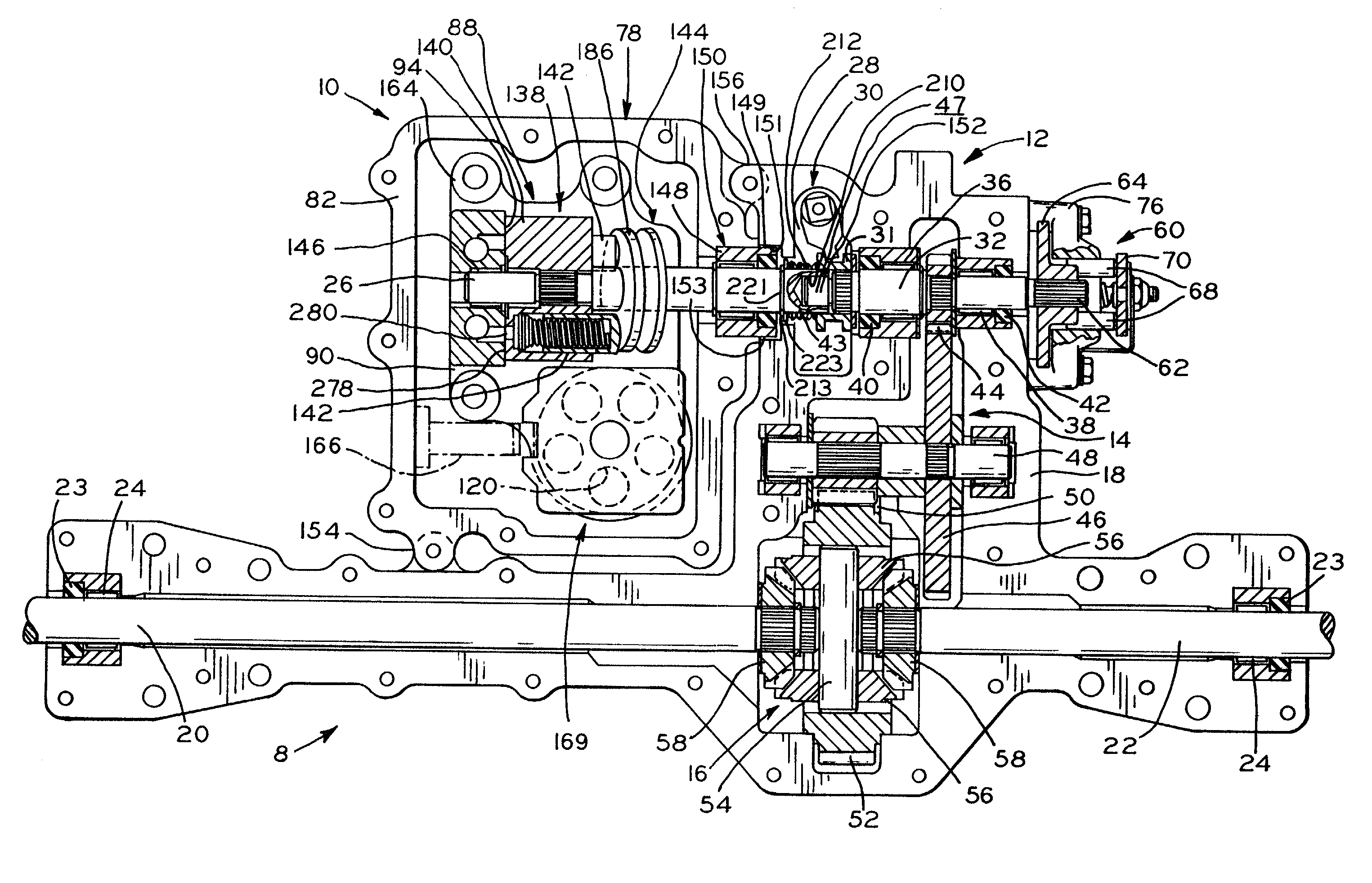
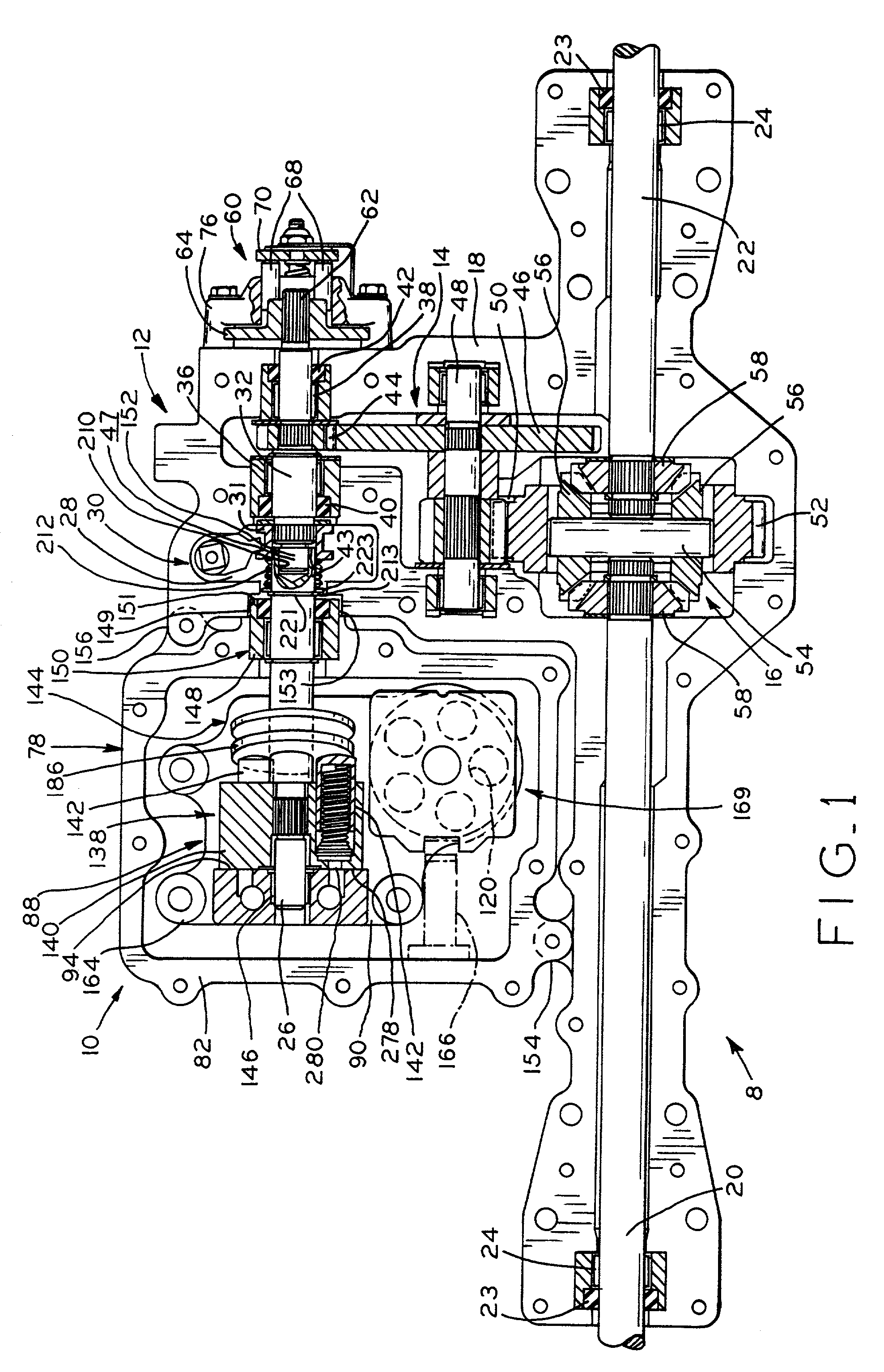
[0050] Referring to FIG. 25, there is shown left hand controlled hydrostatic transaxle 8 including hydrostatic transmission module 10 fastened to axle module 12. Hydrostatic transaxle 8 receives power from a power source (not shown), typically an internal combustion engine, and provides controllable power to axles 20 and 22 which drive wheels attached thereto (not shown). Axle module 12 is provided with a plurality of bolt holes 13 through its structure to secure the unit to the frame (not shown) of an agricultural vehicle or other like receiving structure utilizing transaxle 8. Power is transferred from the power source to transaxle 8 typically by a belt (not shown) engaged with pulley 199 attached to transaxle 8. External controls provided with transaxle 8 include brake lever 70 and control lever 202. Control lever 202 provides control of both speed and direction of the transaxle 8.

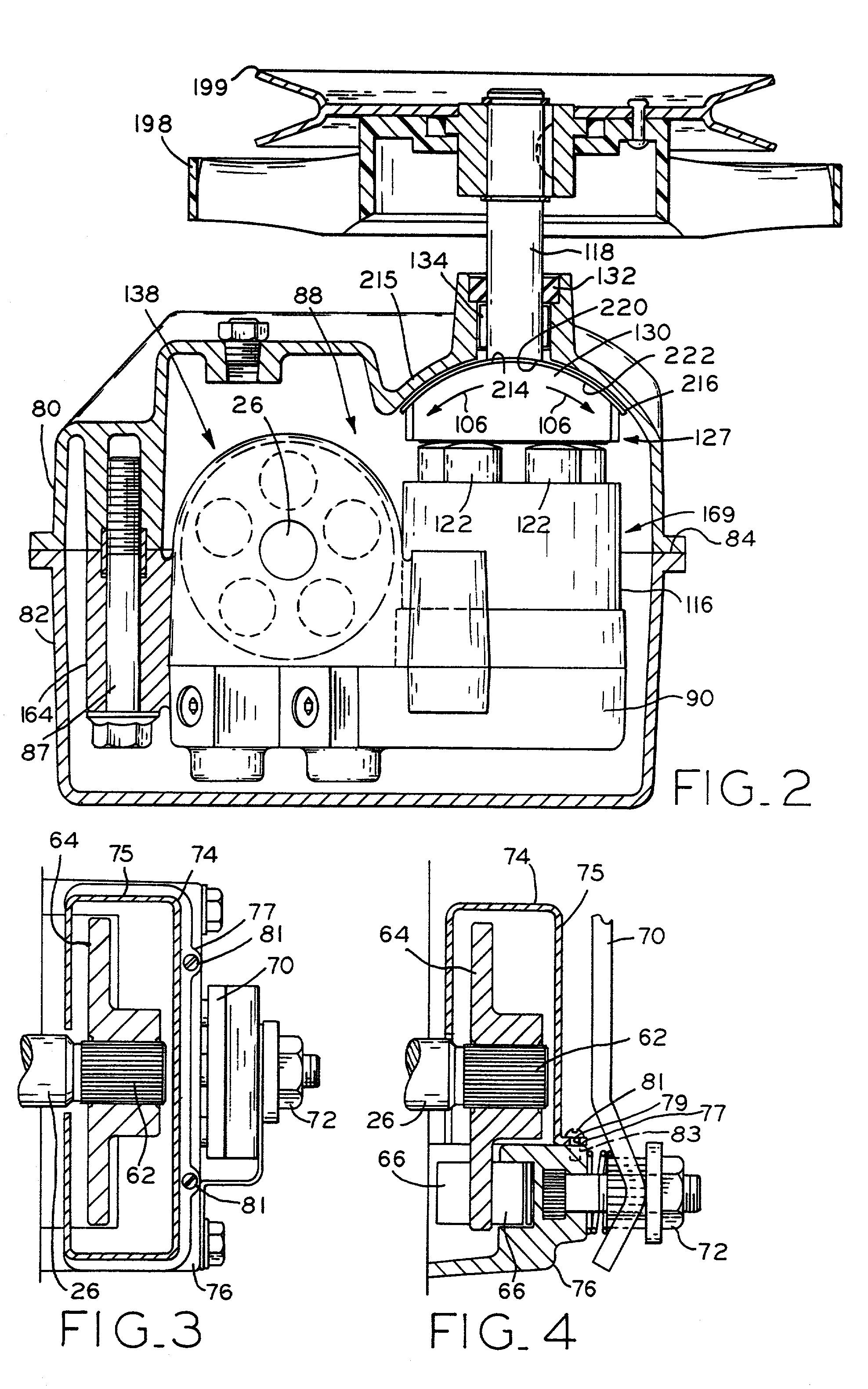
[0051] Referring to FIG. 26, the piloting and coupling structure which provides attachment between a...


PUM

PropertyMeasurementUnit
axes of rotationaaaaaaaaaa
frictionaaaaaaaaaa
homogenousaaaaaaaaaa

Abstract

A modular hydrostatic transaxle includes an axle module removably connected to a hydrostatic transmission module. The axle module includes a differential connected to a reduction gear train and disposed in an axle casing. A pair of axles are connected to the differential and supported within the axle casing. The hydrostatic transmission module comprises a transmission casing separate from the axle casing and hydraulically connected pump and motor disposed in the transmission casing. The motor output connection includes a shaft piloted to an input drive of the reduction gear train, which constitutes the alignment mechanism of the transmission and axle modules. The pump and motor cylinder barrels are hydraulically connected through the pump and motor block at 90.degree. orientation, and a portion of the pump and motor block forms an inclined surface which supports a face of a thrust bearing. At least one homogeneous low friction bearing strip is confined between the swash plate and the interior portion of the casing. A disconnect mechanism includes a spring that urges a sleeve to engage the output and input shafts. The brake disc is disposed on a distal end of the output shaft and a brake cover is fastened to the outer portion of the axle casing and substantially encloses the brake disc.

Description

CROSS REFERENCE TO RELATED APPLICATIONS[0001] This application is related to and claims the benefit under 35 U.S.C. .sctn. 119(e) of U.S. Provisional Applications No. 60 / 119,381 filed Feb. 9, 1999, and 60 / 145,619 filed Jul. 26, 1999.BACKGROUND OF THE INVENTION[0002] The present invention relates to hydrostatic transaxles intended primarily for use in the lawn and garden industry on riding lawnmowers, lawn and garden tractors and the like, but may also be applied to larger implements and vehicles.[0003] Hydrostatic transmissions transmit rotary mechanical motion, typically from an internal combustion engine, to fluid motion, typically oil, and then back to rotary mechanical motion to rotate a pair of drive axles in order to drive the vehicle. The hydrostatic transmission controls the output rotary mechanical motion such that varying output speeds in the forward and reverse directions are possible with a single speed input rotary mechanical motion. Such transmissions have utilized rad...

Claims


Application Information

Patent Timeline
Patent Type & Authority Applications(United States)
IPC IPC(8): B60K17/10F16H39/08F16H39/14
CPCB60K17/105B60Y2200/223F16H39/08F16H39/14F16H47/02Y10T74/19149Y10T29/49904Y10T29/49826Y10T74/2186
Inventor JOLLIFF, NORMAN E.RUEBUSCH, RICHARD T.DOWEN, GORDON C.TWADDLE, GARY G.
Owner HUSQVARNA AB
Why Eureka
Try Eureka