Differential quench method and apparatus

Inactive Publication Date: 2002-09-19
UNTRA PREMIUM OILFIELD SERVICES LTD
View PDF0 Cites 23 Cited by
  • Summary
  • Abstract
  • Description
  • Claims
  • Application Information

AI Technical Summary

Benefits of technology

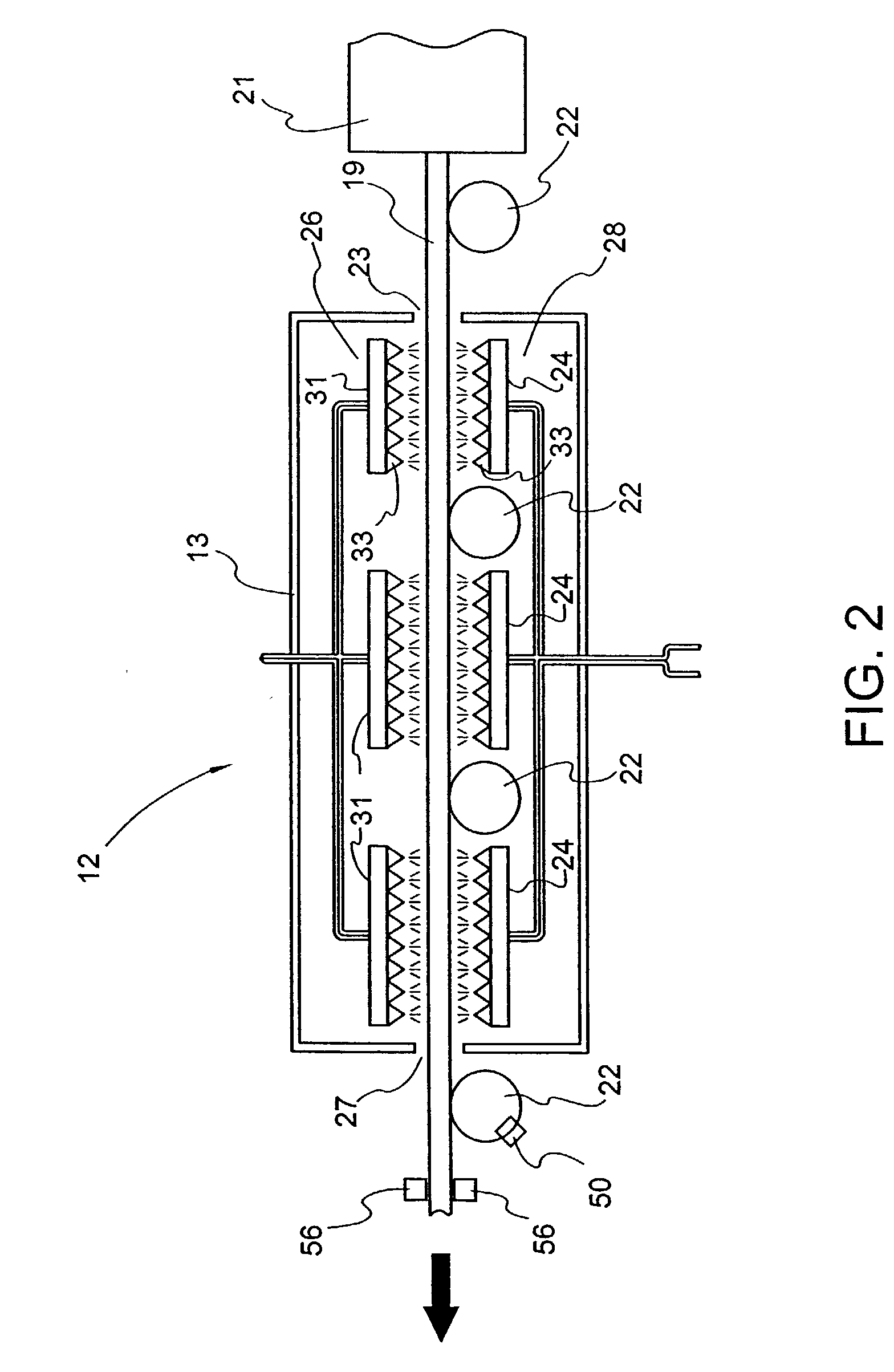
0022] The apparatus for providing each spray group may conveniently comprise one or more longitudinally aligned banks of nozzles, each bank comprising a series of nozzles extending parallel to the direction of the casting line. Optionally, other nozzle groups may comprise transversely aligned rows of nozzles extending perpendicular to the direction of the casting line. Preferably one array of nozzles is positioned above the steel and another counterpart array underneath the steel, so that upper and lower surfaces of the steel may be quenched in a balanced, uniform manner.
0023] Each spray group may advantageously comprise at least one dedicated bank. Depending upon the width of the slab, some of the banks may not overlap the slab as it passes by the spray. Advantageously, for a selected transverse width of the steel product, only those banks of sprays directly above and below the product are operated, leaving the other banks idle. This practice tends to facilitate transverse

Problems solved by technology

Problems encountered with plate steel product produced by such continuous casting mills include the tendency for areas around one or more surfaces of the steel product to exhibit brittleness, cracking, sponging, and other surface defects (hereinafter collectively referred to as "surface defects" for convenience).
Surface defects are especially prevalent after the interim steel product is subjected to downstream rolling or other stresses.
Although the causes of such surface defects are not completely understood, it has been observed that surface defects tend to occur frequently in steel products having surfaces that are at or above the steel's austenite-to-ferrite transformation start temperature (Ar.sub.3) when the product exits the caster assembly, and which cool to a temperature above the steel's austenite-to-ferrite transformation completion temperature (Ar.sub.1) as the product enters the reheat furnace, then are reheated to a temperature above the transformation start temperature when the product is inside the reheat furnace.
The presence of these elements on grain boundaries and/or the development of precipitate-free zones adjacent to grain boundaries can be detrimental to the ductility of the steel product and may also contribute to the manifestation of on

Method used


Image

  • Differential quench method and apparatus
  • Differential quench method and apparatus
  • Differential quench method and apparatus

Examples


first embodiment

[0082] In this embodiment, the longitudinal supply pipes 82 are connected to associated respective water control valves 84a, 84b, 84c and water pressure regulators 85a, 85b, 85c. Similarly, the longitudinal supply pipes are connected to associated respective air control valves and pressure regulators (not shown FIG. 5) In a manner similar to the transverse spray control described in the first embodiment, the control valves 84 and pressure regulators 85 regulate the fluid flow rate and pressure for the three longitudinally spaced banks 76. Such longitudinal control is useful in countering non-uniform longitudinal cooling in the strand, which may for example, be caused by anomalies in the orderly progress of the steel through the caster assembly 21. For example, for a given length of the strand, the leading portion may be at a higher temperature than the trailing portion at a given line location. In this connection, the longitudinal-control array may be programmed to apply a higher in...

example

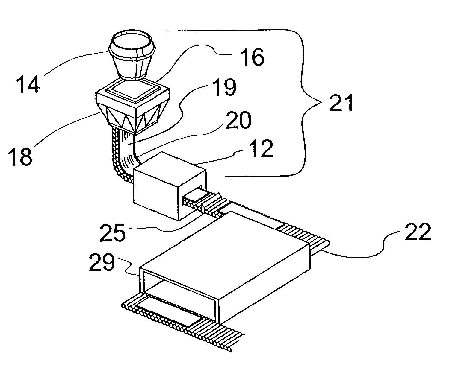
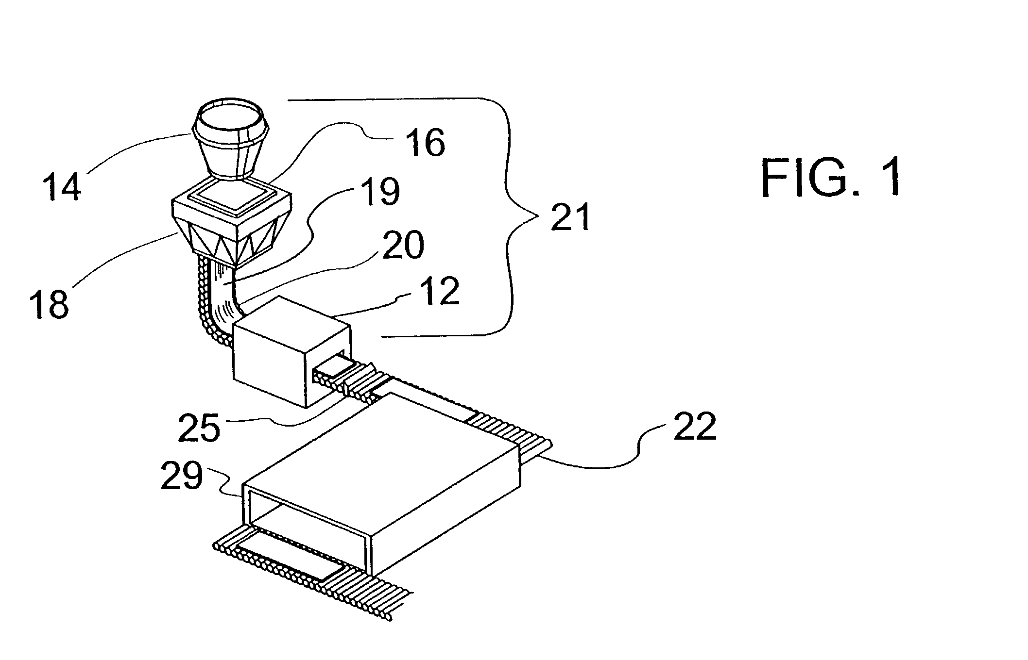
[0089] Consider a steel casting about 6 inches thick, and of variable width of anywhere between about 40 inches and 125 inches, being produced at normal casting line speeds of anywhere between about 30 inches per minute and 75 inches per minute. Assume that a quench penetration of at least about a half-inch from the surface is targeted, and that the quench will reduce surface temperature of the casting from a temperature of the order of (982.degree. C.) 1800.degree. F. to a temperature of the order of 538-704.degree. C. (1000-1300.degree. F.).

[0090] Engineering considerations, notably the principle of simplification, make it desirable to control nozzles in banks of longitudinally aligned nozzles. Four groups of top nozzle banks can be arrayed over the maximum width of the casting, including:

[0091] first, a central group of at least 1, and perhaps 3 or 5 banks of nozzles;

[0092] second, a mid-inner group comprising, say, 4 banks of nozzles, two on either side of the centre line and ly...


PUM

PropertyMeasurementUnit
Angleaaaaaaaaaa
Temperatureaaaaaaaaaa
Lengthaaaaaaaaaa

Abstract

Surface defects in rolled steel are remedied by quenching a surface layer of the steel product downstream of the caster and upstream of the reheat furnace by transversely differentiated quenching to match the transverse temperature profile of the steel product. The flow rate of the quench spray is differentially adjustable across the width and optionally the length of the steel product. An array of spray nozzles controlled in transversely or longitudinally arranged groups provides the quench spray.

Description

RELATED APPLICATIONS[0001] This application is a divisional of U.S. application Ser. No. 09 / 350,319 filed Jul. 9, 1999 entitled "Differential Quench Method and Apparatus", which is a continuationin-part of U.S. application Ser. No. 09 / 113,428 filed Jul. 10, 1998 entitled "Differential Quench Method and Apparatus", both of which are incorporated herein by reference.FIELD OF THE INVENTION[0002] The present invention comprises methods of quenching a continuously cast steel product upstream of a reheat furnace that brings the steel to a uniform initial rolling temperature. One purpose served by the invention is to eliminate or reduce the incidence and severity of surface defects in the steel that occur during reduction rolling. There are a number of inventive aspects of the applicant's methods that collectively may comprise more than one invention, but for convenience, reference will be made to "the invention" on the understanding that the term covers the collectivity of inventions clai...

Claims


Application Information

Patent Timeline
IPC IPC(8): B21B1/34B21B1/46B21B15/00B21B37/74B21B45/00B21B45/02C21D8/02
CPCB21B1/34B21B1/466B21B37/74B21B45/004B21B45/0218B21B2015/0014B21B2015/0071C21D8/021C21D8/0226C21D2211/002C21D2211/008
Inventor FRANK, WILLIAM R.DORRICOTT, JONATHANCOLLINS, LAURIE E.RUSSO, JOSEPH D.BOECKER, ROBERT J.WALES, BRIAN H.
Owner UNTRA PREMIUM OILFIELD SERVICES LTD
Why Eureka
Try Eureka