

Piezoelectric structure, liquid ejecting head and manufacturing method therefor
a technology of liquid ejecting head and piezoelectric structure, which is applied in the direction of generator/motor, device material selection, printing, etc., can solve the problems of difficult piezoelectric film fine processing, vibration production, and difficulty in producing thin piezoelectric film
Inactive Publication Date: 2002-10-03
CANON KK +1
View PDF7 Cites 43 Cited by
- Summary
- Abstract
- Description
- Claims
- Application Information
AI Technical Summary
Benefits of technology
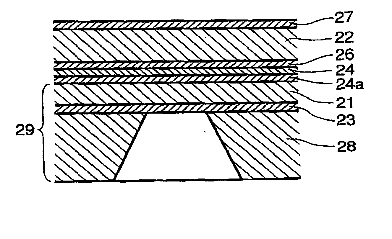
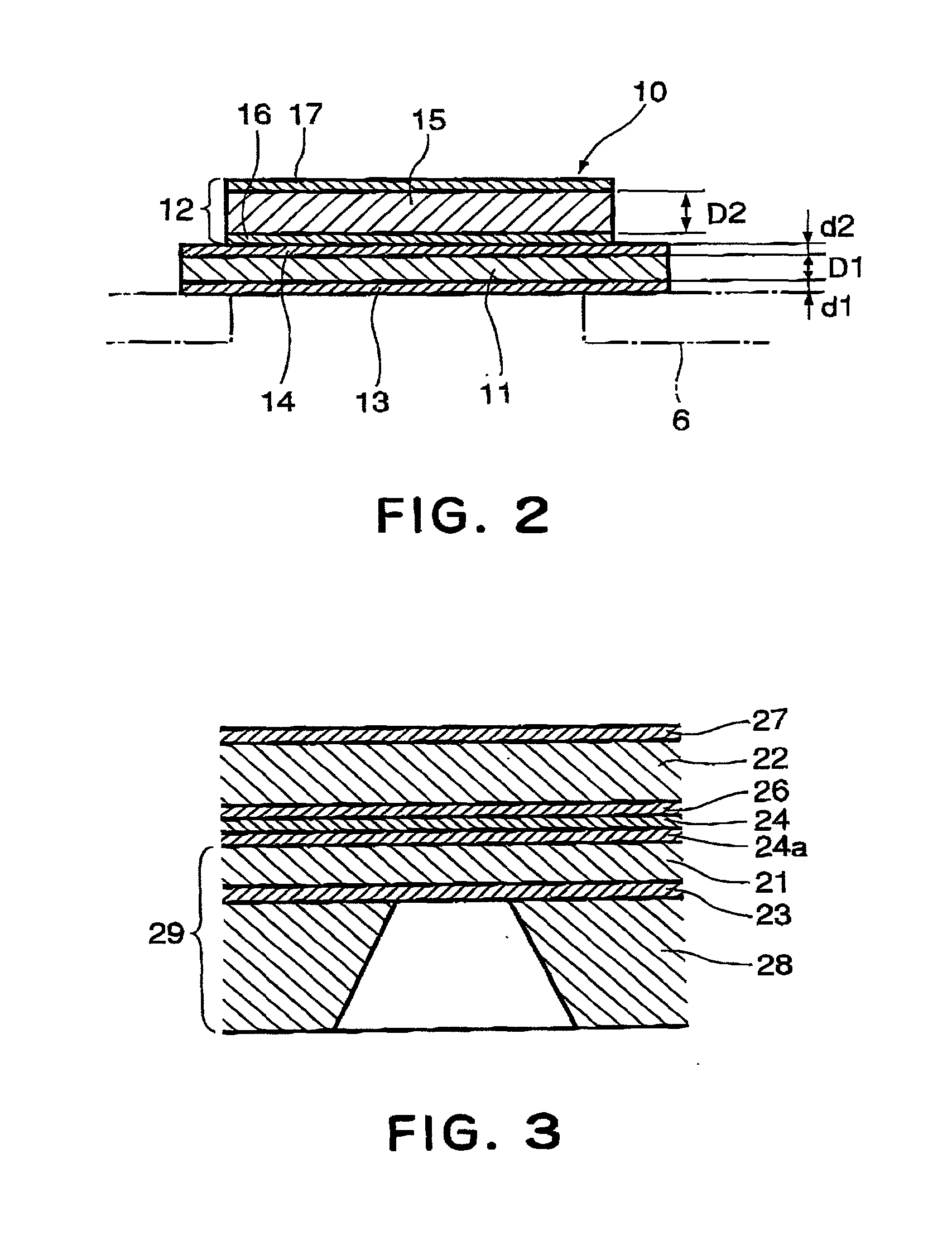
[0017] According to the present invention, the vibrational plate constituting the piezoelectric structure and having a monocrystal or polycrystal structure is sandwiched by oxide materials, so that even if fine cracks are produced as a result of repetition of mechanical displacement, the strength of the vibrational plate per se is maintained, and the adhessiveness relative to the piezoelectric film is not deteriorated, and therefore, durable devices can be provided.
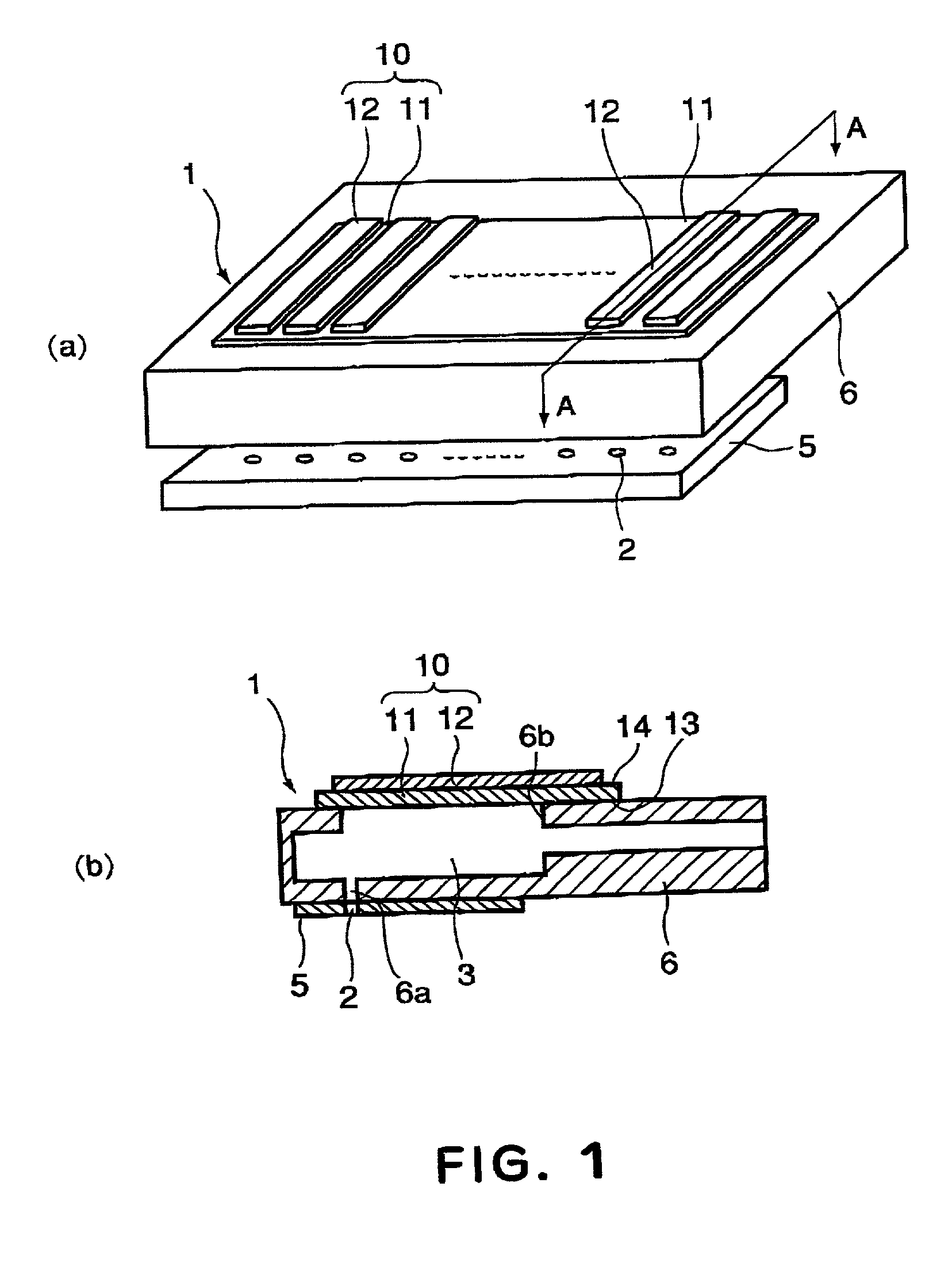
[0019] By incorporating such a piezoelectric structure, a device having a high durability, high density, large ejection power with high frequency, in which the performance of each of the liquid ejection outlets are uniform can be provided. In addition, by producing the piezoelectric member and the vibrational plate or the like as thin films, the micro fabrication usable in the semiconductor process is available. In addition, a liquid ejecting head having a high curability, electrostrictive / piezoelectric particularly property, a large length, a stabilized reliability, can be provided.
Problems solved by technology
With such a structure, a predetermined voltage is applied to the piezoelectric element to collapse and expand the piezoelectric element, thus producing a vibration.
However, the piezoelectric film is manufactured by forming PbO, ZrO.sub.2 and TiO.sub.2 powder into a sheet, and then baking it, and therefore, it is difficult to produce a thin piezoelectric film such as not more than 10 .mu.m.
Because of this, fine processing of the piezoelectric film is difficult, and this makes the downsizing of the piezoelectric element difficult.
In the case that piezoelectric film is produced by baking the powder, the influence of the grain boundary of crystalline is not negligible, and therefore, good piezoelectric particularly property cannot be provided.
As a result, the piezoelectric film produced by baking the powder does not exhibit satisfactory piezoelectric particularly property for ejecting the liquid such as ink in the thickness is not more than 10 .mu.m.
For this reason, a small size liquid ejecting head having necessary properties for liquid ejection has not been accomplished.
This places a limit to a size, and it is difficult to arrange a great number of liquid ejection outlets (nozzles).
However, with the system, there arise the following problems:
(2) the oriented PZT layer Can be provided only on a monocrystal substrate of monocrystal MgO or the like which is expensive, and therefore, the process is very expensive. In addition, there is a limited in the size of the monocrystal substrate of MgO, and therefore it is not possible to produce a large area substrate.
(3) Using the method disclosed in this publication, the connection occurs in the neighborhood of the piezoelectric member or the connecting portion between the piezoelectric member and the member constituting the pressure chamber (liquid chamber) by adhesive material or the likes. In the region of micromachining, the reliability against the repetition of the stresses or the like is not sufficient.
(4) The vibrational plate in the method disclosed in the application, is directly contacted to the liquid such as ink in the liquid ejecting head, and in addition, in the manufacturing process, it is contacted to the acid, alkali or another chemical agent, and therefore, it is not possible to produce reliable liquid ejection elements. Moreover, the manufacturing process is complicated, and the liquid ejecting heads are expensive.
This method is not suitable for a micro fabrication, and it is not possible to provide a film thickness of the piezoelectric film not more than 10 .mu.m.
Method used
View moreImage
Smart ImageViewing Examples

Examples
example 6
[0050] Au / / PZT(001) / / SRO(001) / / Si(100) / / SiO.sub.2
example 7
[0051] Al / / PZT(111) / / SRO(111) / / Si(111) / / SiO.sub.2
example 8
[0052] Au / / PZT(111) / PT(111) / / Pt(111) / / YSZ(100) / SiO.sub.2 / / Si(100) / / YSZ(100-)
Login to View More PUM
| Property | Measurement | Unit |
|---|---|---|
| thickness | aaaaa | aaaaa |
| thickness D1 | aaaaa | aaaaa |
| thickness | aaaaa | aaaaa |
Abstract
A piezoelectric structure includes a vibrational plate; a piezoelectric film; the vibrational plate including a layer of a monocrystal material, a polycrystal material, a monocrystal material doped with an element which is different from an element constituting the monocrystal material, or a polycrystal material doped with an element which is different from an element constituting the polycrystal materials, and oxide layers sandwiching the aforementioned layer, the piezoelectric film has a single orientation crystal or monocrystal structure.
Description
FIELD OF THE INVENTION AND RELATED ART[0001] The present invention relates to a piezoelectric structure, a liquid ejecting head and a manufacturing method therefor.[0002] Recently, printers using liquid ejection recording devices are widely used as printing apparatuses for personal computers or like, because of the high printing property, easy manipulation, low cost or the like. The liquid ejection recording devices are of a type in which a bubble is generated in liquid such as ink by thermal energy, and the droplet is ejected by the resulting pressure wave, a type in which the droplet is sucked and discharged by electrostatic force, a type in which a pressure wave is produced by a vibration element such as a piezoelectric element, or the like.[0003] In a liquid ejecting apparatus using a piezoelectric element, there are provided a pressure chamber in fluid communication with a liquid supply chamber, a liquid ejection outlet in fluid communication with the pressure chamber, a vibrat...
Claims
Login to View More Application Information
Patent Timeline
 Patent Type & AuthorityApplications(United States)
IPC IPC(8): B41J2/045B41J2/055B41J2/135B41J2/14B41J2/145B41J2/16H01L41/08H01L41/09H01L41/18H01L41/22H01L41/29H01L41/319H02N2/00
CPCB41J2/161B41J2/1628B41J2/1629B41J2/1632B41J2/1646Y10T29/49401H01L41/0973Y10T29/4913Y10T29/42Y10T29/49128H01L41/0815H10N30/2047H10N30/708B41J2/16
InventorUNNO, AKIRAYONEHARA, TAKAOFUKUI, TETSUROMATSUDA, TAKANORIWASA, KIYOTAKA
OwnerCANON KK