

Optical waveguide grating and method and mask for forming same
a technology of optical waveguides and fiber bragging, which is applied in the direction of optical waveguide light guides, instruments, optical light guides, etc., can solve the problems of complex formation process, only applicable methods, and difficult to achieve the above-mentioned method to produce a high-efficiency fiber bragging
Inactive Publication Date: 2002-10-17
WASEDA UNIV
View PDF8 Cites 33 Cited by
- Summary
- Abstract
- Description
- Claims
- Application Information
AI Technical Summary
Problems solved by technology
However, the ultraviolet light irradiation method has a defect in that the method is only applicable for a special photosensitive optical waveguide in which refractive index change occurs with the ultraviolet light irradiation.
The formation process therefore becomes complex.
However, it is quite difficult for the above-mentioned method to produce a high efficient fiber Bragg grating.
The difficulty is due to the spread of the implanted ions.
However, even in the case that the projected range of the implanted ions is small; if the lateral spread of the implanted ions is not taken into account, two adjacent gratings overlap and the efficiency of the fiber Bragg grating becomes worse.
However, in this method, it is virtually impossible to form a thick refractive index change portion, since the projected range of the ions is small and the grating is formed only near the surface of the core.
However, even in the case that the cladding is thin and / or the implanted ions are heavy, there still exists the lateral spread of the ions and two adjacent gratings overlapping.
Thus the efficiency of the fiber Bragg grating becomes worse.
If an acceleration energy of more than 50 MeV is required, the ion accelerator will be so expensive that the method is of no practical use.
As mentioned above, there is a problem in the conventional ion implantation methods in that the methods are not applicable for the fabrication of a fiber Bragg grating in an optical waveguide with a thick cladding of tens of microns.
Furthermore, the conventional ion implantation methods are not good enough for the fabrication of a high efficiency fiber Bragg grating even in an optical waveguide with a thin cladding or without cladding.
However, masks suitable for the method have not been designed so far.
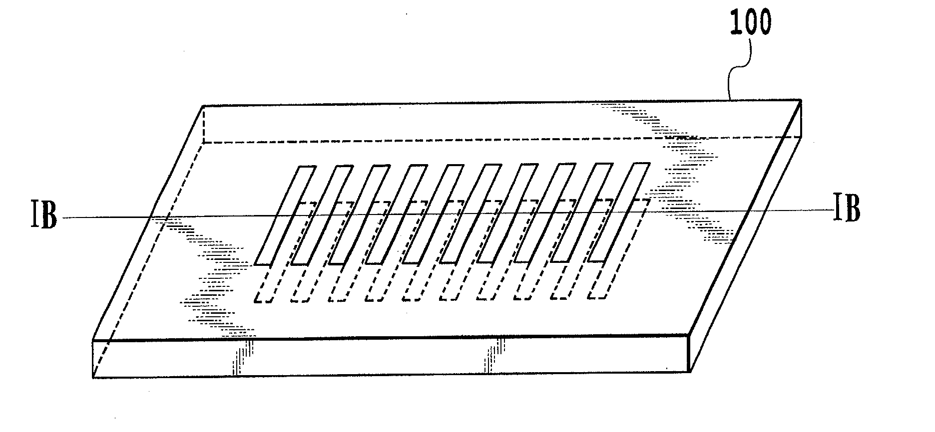
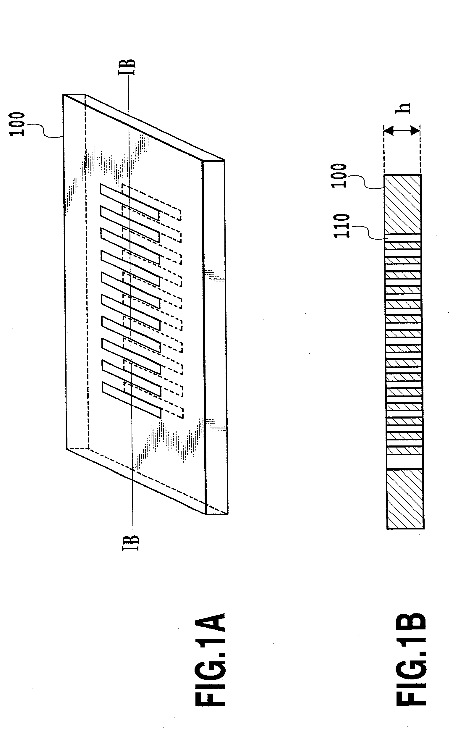
The width of the slit should be as small as possible, since a wide slit makes the period of a fiber Bragg grating larger, which results in the deterioration of the efficiency of the fiber Bragg grating.
However, such small patterns are not practical and the mask will be quite expensive.
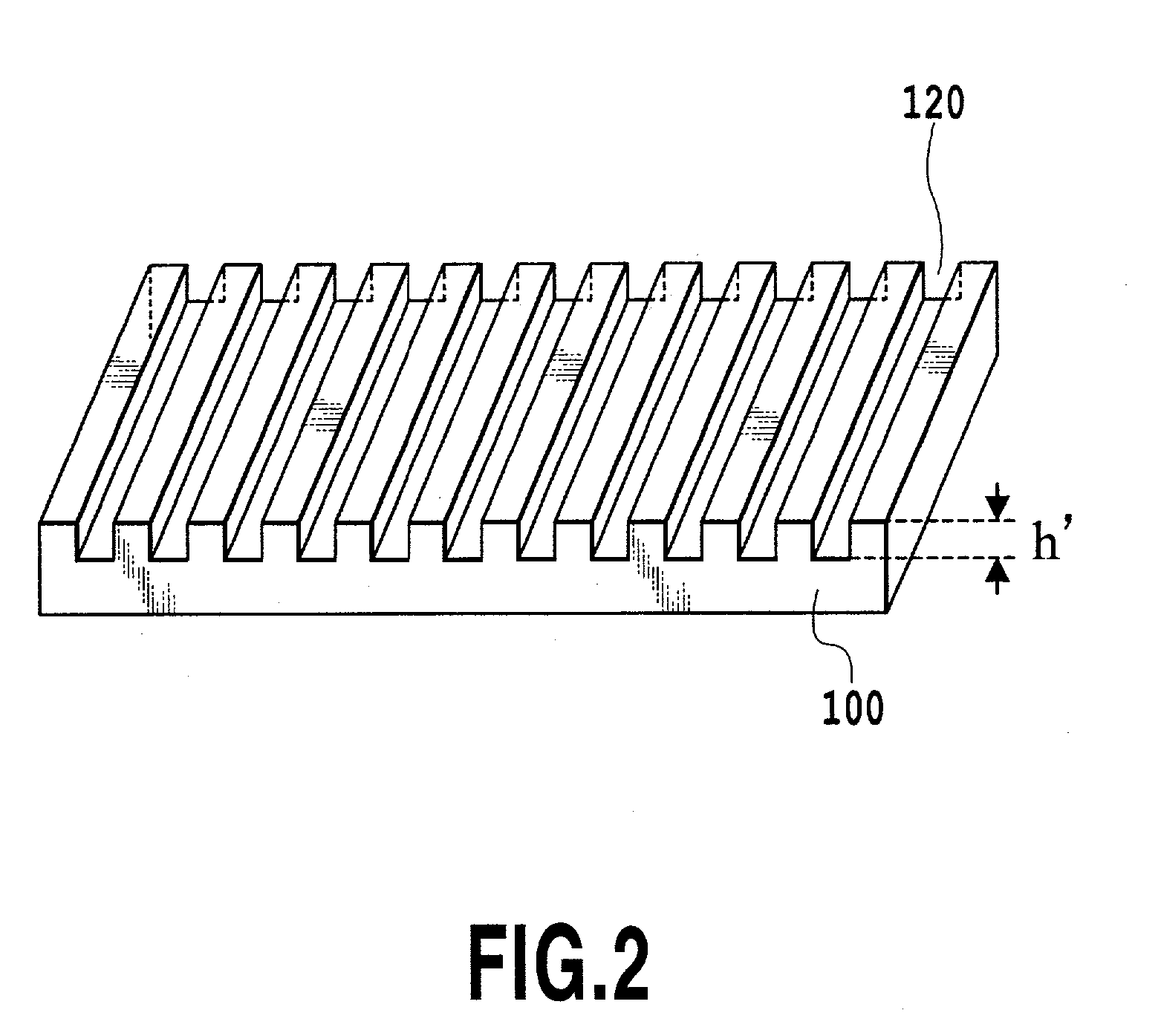
However, masks with thick h or h' are quite expensive.
Ion implantation into silica-based glass causes a densification of the glass, which results in a refractive index increase.
However, ions of heavy atoms require high acceleration energy to obtain long projected ranges.
Since the diffracted lights that satisfy the coupling condition with leaky modes have wavelengths shorter than the Bragg reflection wavelength, undesirable radiation losses at the shorter wavelength region appear.
Therefore, the ions form the fiber Bragg grating in the center of the core, even though the efficiency of the fiber Bragg grating is not better than that formed by the hydrogen ions accelerated with 1.2 MeV.
In the method that forms the grating shape refractive index change in the portion where the ions pass through, the efficiency of the refractive index change is low, and as a result, high ion doses are required.
However, if the intensity distribution shown in FIG. 11B is given to the refractive index changes, the average refractive index in the fiber Bragg grating becomes non-uniform as indicated by the broken curve.
However, because of the spread of the implanted ions, the change in the slit width of the mask results in a change in the extent of the overlap of two adjacent gratings, and the efficiency of the fiber Bragg grating is deteriorated.
If the diameter or the width of the ion beam is greater than the length of the fiber Bragg grating, it is difficult to form the apodisation by the present method.
However, ions are not able to pass through films 81, which are too thick.
Method used
View moreImage
Smart ImageViewing Examples

Examples
Embodiment Construction
]
[0145] The above-mentioned ion implantation conditions concerned with the present invention are applied not only for the fiber Bragg grating but also for the long period grating, and the above-mentioned embodiments of the present invention are also applied for the long period grating.
[0146] The present invention has been described in detail with respect to preferred embodiments, and it will now be apparent from the foregoing to those skilled in the art that changes and modifications may be made without departing from the invention in its broader aspect, and it is the intention, therefore, in the appended claims to cover all such changes and modifications as fall within the true spirit of the invention.
Login to View More PUM
 Abstract
An optical waveguide grating is formed in an optical waveguide core and / or in an optical waveguide cladding where an electric filed of light propagating in the core is spreading by implanting accelerated ions through a mask to the optical waveguide. The mask has enough thickness to prevent the ions irradiated to the masked parts from reaching the portion where the grating is formed. The acceleration energy of the ions is chosen to make the lateral straggling of the implanted ions in the optical waveguide less than three fourths of the period of the grating, or the acceleration energy is chosen to make all or a part of the implanted ions pass through the portion where the grating is formed.
Description
[0001] This application is based on Japanese Patent Application Nos. 2001-113041 filed Apr. 11, 2001, 2001-171087 filed Jun. 6, 2001 and 2001-379173 filed Dec. 12, 2001, the contents of which are incorporated hereinto by reference.[0002] 1. Field of the Invention[0003] The present invention relates to an optical waveguide grating, which is commonly known as an optical fiber grating or OFG, a method for forming the optical waveguide grating and a mask for forming the optical waveguide grating. More particularly, the present invention relates to the mask design and the ion implantation method for forming the optical waveguide grating by forming periodic refractive index changes in the wave-guiding portion of an optical waveguide with refractive index changes induced by implanting ions accelerated with high acceleration energy. The wave-guiding portion is commonly called a core for optical fibers and is referred to as `core` or `optical waveguide core` hereafter. The optical waveguide ...
Claims
Login to View More Application Information
Patent Timeline
 IPC IPC(8): G02B6/122G02B6/02G02B6/124G02B6/13
CPCG02B6/02123G02B6/124G02B6/02142
InventorFUJIMAKI, MAKOTO
OwnerWASEDA UNIV